How to Fix a Faulty LCD Projector
How to Fix a Faulty LCD Projector


Many people and companies are using LCD projectors nowadays. In different universities, classes use LCD projectors in discussions and the same for business meetings and presentations as they are used by many corporations. People now also use the projectors as part of their home entertainment systems.
What is an LCD Projector?
LCD projector refers to a kind of video projector that is used to display or “project” an image, video, and computer data on a flat exterior or simply a screen. In order to project images and other similar presentations, light is projected from the Metal halide lamp to a prism placed in between the three poly silicone panels. Despite the advancement of an LCD projector, there are times that it simply malfunctions. There are different kinds of LDC problems and for every faulty LCD projector, there is a corresponding solution.
Materials Needed
Basically, the main thing to do in fixing a faulty projector is to test and then replace or change the specifications. For image distortions, it’s the setting of the projector and the computer that should be changed. For faulty images the following might be needed:
Screwdriver
Lamp replacement
Mirror replacement
Pliers or tweezers
Fixing LCD Projector that do not Display Computer Images
If the projector shows DVD, CCTV, and VHS but will not project the image from the computer, the following steps should be done.
Using the manual from the manufacturer, check the computer’s refresh rate. Adjust the settings of the refresh rate.
Go to start, click Control Panel then proceed to Appearance and Themes then go to Display.
Go to Settings Tab then proceed to the Advanced Option. There should be the Monitor options.
Checking the refresh rate in the manual of the projector, adjust the settings accordingly.
Repairing Projector with Yellowish Image
Step 1: Check the LCD Panel
A yellow image from the projector is usually the result of a broken LCD panel. To see which panel is broken, pop the cover of the projector using the screwdriver. Make sure to refer first to the manual before opening the projector. Inside the projector, mirrors are positioned to separate each colored LCD panel: red, blue and green. The panels are placed around a prism that mixes the three colors together to display an image.
Step 2: Test Each LCD Panel
In order to test each panel, the projector has to be turned on. Make sure that no sensitive parts are touched to avoid problems. Cover each panel with a paper or cardboard and see which panel does not reflect the color well. The malfunctioning panel will not be able to respond to a signal. It will also show which panel does not reflect the right form of the image.
Step 3: Replace the Malfunctioning Part
Using pliers or tweezers, take out the malfunctioning panel. This step may not be applicable to all projectors so check with the manual how to detach the panels. Once the malfunction part is taken out, position the replacement.
Step 4: Check the Panels Again
Check the panel by shielding it again. See if it already reflects the right color and the correct image quality.
Step 5: Cover the Projector
Screw on the lid and test the projector.
Merch Source Projector Entertainment II Speaker Replacement
Introduction
Muffled sound? Distorted sound? No sound? No problem! Simply use this guide to regain awesome audio in your projector. To follow this guide, you should have the following parts handy:
Step 1 Outer Casing
-
Flip the projector onto its back and unscrew the nine 15mm screws using the Phillips #0 screw driver.
Step 2
-
Flip the projector right side up and unscrew the two 12mm screws on the light bulb panel located at the rear of the projector with a Phillips #0 screw head.
Step 3
-
Using your hands, gently pry the top and bottom of the projector casing apart.
Step 4 Speaker

-
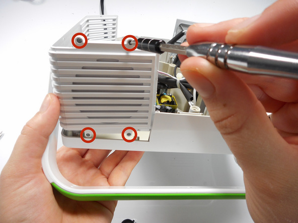
Locate the 2 screws on the handle casing. These screws are mirrored on the handle attachment on the other side panel as well.
-
Unscrew the two 16mm screws using the Phillips #0 screw driver. Repeat for the opposite side panel.
Step 5
-
Lift up on the side panel and speaker attachment to slightly dislodge it.
-
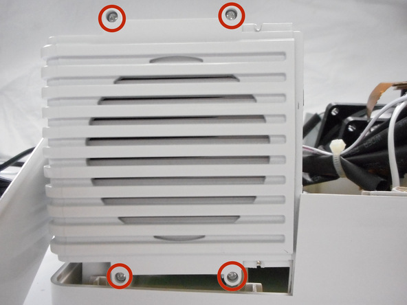
Unscrew the four 9mm Phillips screws with a Phillips #0 screw driver, located on the outside of the projector casing.
Step 6
-
Once the side panel door has been lifted out of the bottom casing, it can swing freely.
-
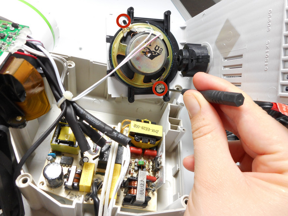
Rotate the side panel door forward so that you can access the screws on the speaker.
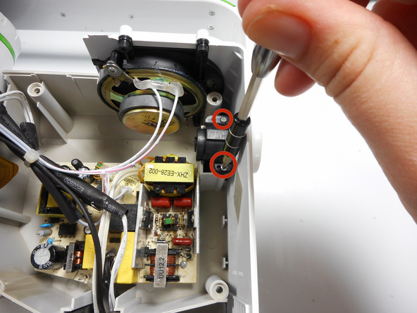
-
Unscrew the two 10mm screws with a Phillips #0 screw driver.
-
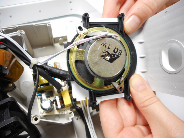
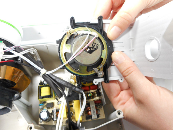
Lift the side panel and speaker out from the projector casing.
-
Using your hands, slide the speaker outward from the side panel.
Step 8
Edit
![Image 2/3: Need some help? Follow this [guide|750|guide] to learn soldering basics.](http://safe-land.ir/wp-content/uploads/2016/12/HALXlXV5KKunfIHf.medium)
-
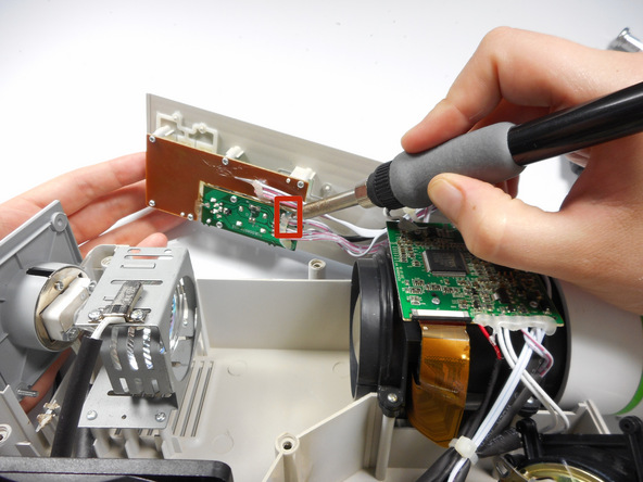
Locate the two speaker wires connected to the sound and audio motherboard on the left panel opposite of the speaker. Unsolder these connections with a soldering iron.
-
Once the wires are disconnected, in order to fully remove the speaker you may need to cut the plastic bands holding the speaker wires in place.
Merch Source Projector Entertainment II Outer Lens Replacement
Introduction
Do you have a blurry image or a broken outer lens? Follow these step by step instructions to learn how to disassemble the projector and remove the outer lens for your repairs.
Step 1 Outer Casing
Flip the projector onto its back and unscrew the nine 15mm screws using the Phillips #0 screw driver.
Step 2
Flip the projector right side up and unscrew the two 12mm screws on the light bulb panel located at the rear of the projector with a Phillips #0 screw head.
The bottom right panel screw does not come completely out the panel door.
Step 3
Using your hands, gently pry the top and bottom of the projector casing apart.
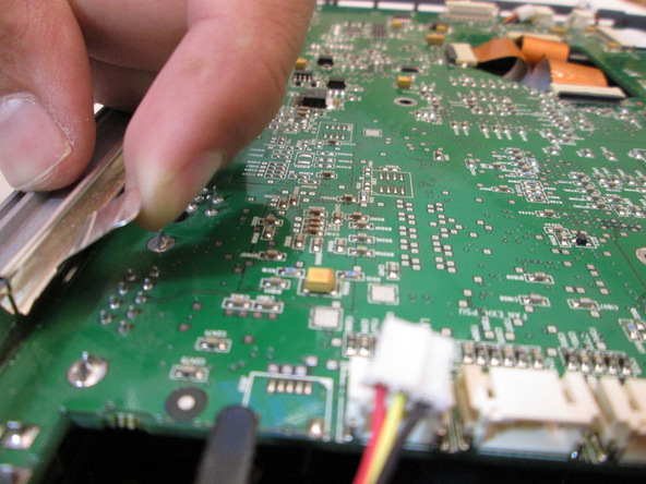
Step 4 Ribbon Cable Detachment
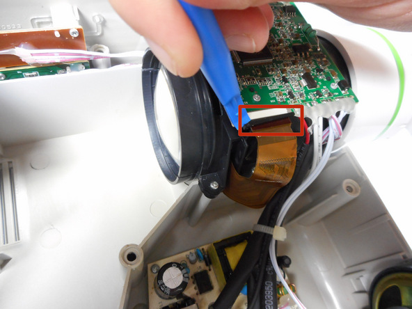
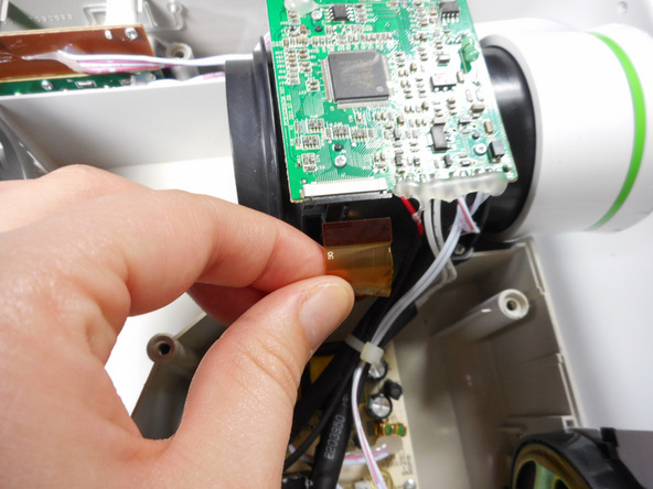
Use the plastic opening tool to gently disengage the black clip housing from the ribbon cable.
Once the ribbon cable is disengaged gently pull the cable off the motherboard.
Once the housing is disengaged, the ribbon cable should slide out easily. Do not pull too hard on the ribbon cable as it is very fragile.
Step 5 Motherboard Detachment
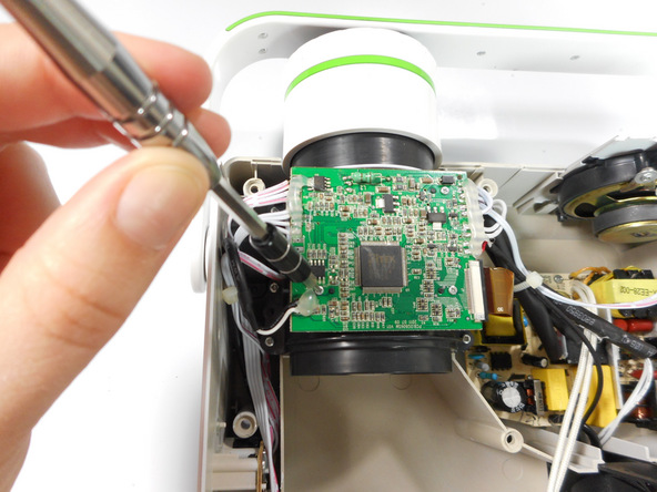
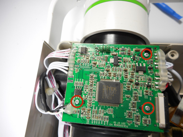
Unscrew the three 7 mm screws from the motherboard with the Phillips #0 screw driver.
Once loose, lift the motherboard off of the lens casing, and move it away from the workspace.
Be sure not to damage any of the wires atached to the motherboard.
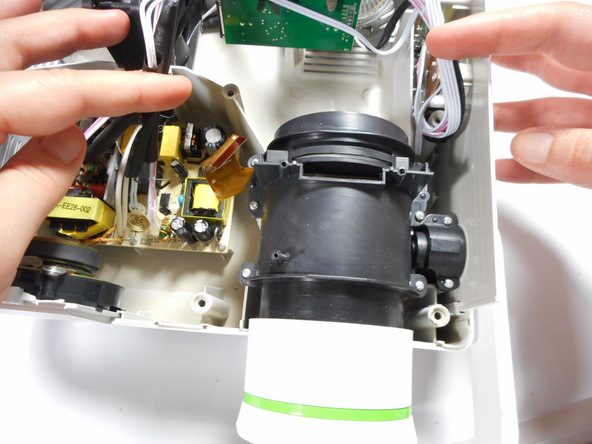
Step 6 Lens Casing Detachment
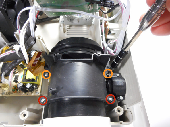
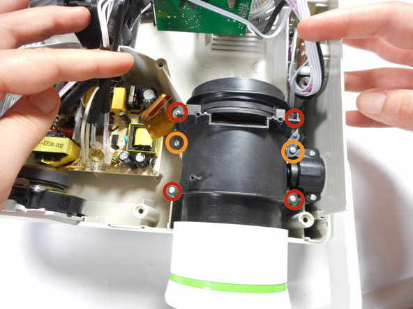
Unscrew the four 15mm Phillips screws using the Phillips #0 screw driver.
Unscrew the two 12mm Phillips screws using the Phillips #0 screw driver.
Gently remove the entire lens casing from it’s position.
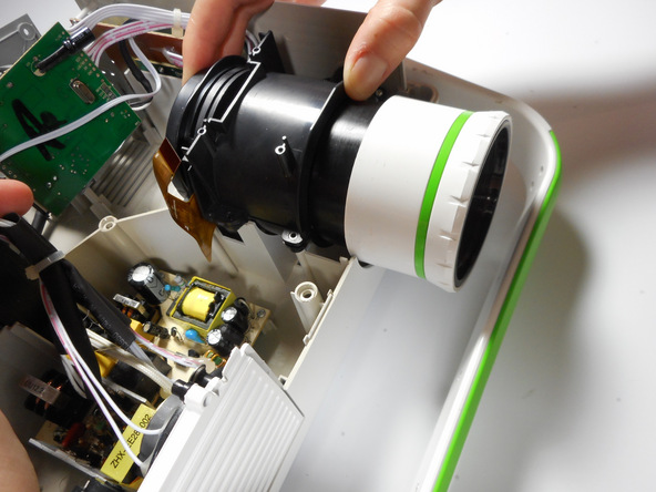
Step 7 Lens Casing Seperation
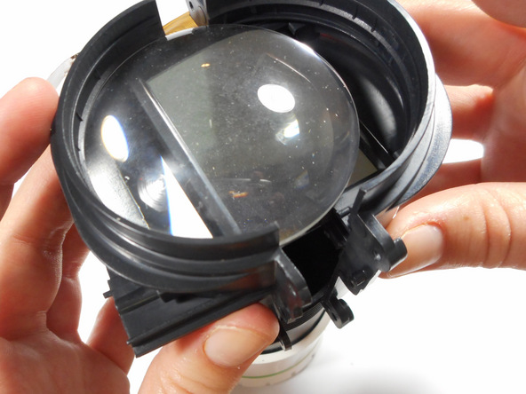
Using the plastic opening tool, slightly separate the casing holding the large lens in place.
Separate the casing completely from the inner lens using your hands.
This should release the outer lens and it’s immediate casing.
As you separate the outer casing, the lens and digital display box may fall out of their encasement.
Although there are threads connecting the outer lens casing and the inner lens casing, do not be fooled. The outer lens casing cannot be disconnected by unscrewing it.
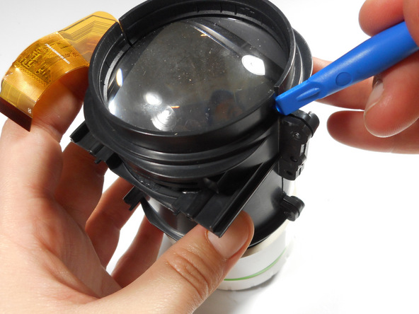
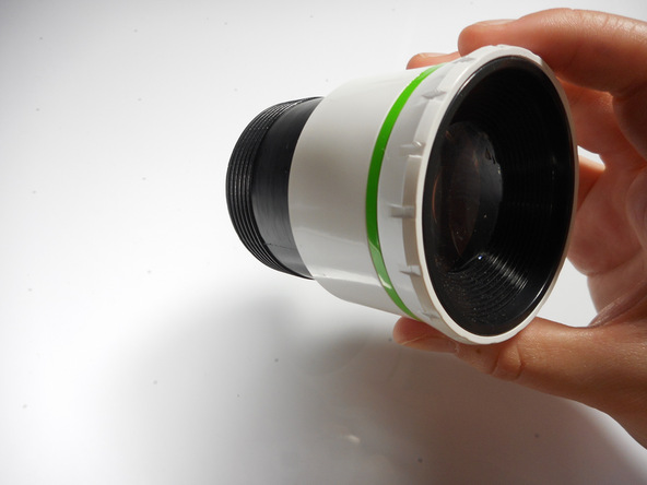
Step 8 Outer Lens Casing Seperation
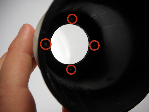
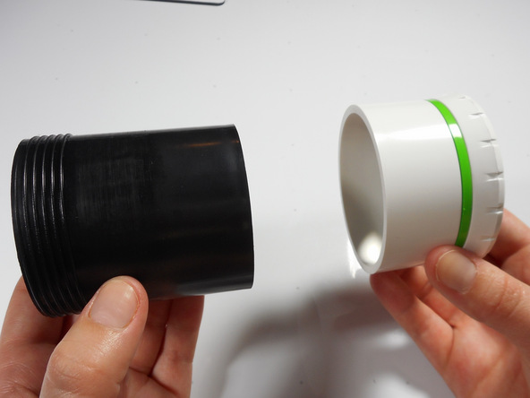
Unscrew the four 8mm Phillips screws at the base of the outer lens casing using the Phillips #0 screw driver.
Separate the white outer casing from the black outer casing.
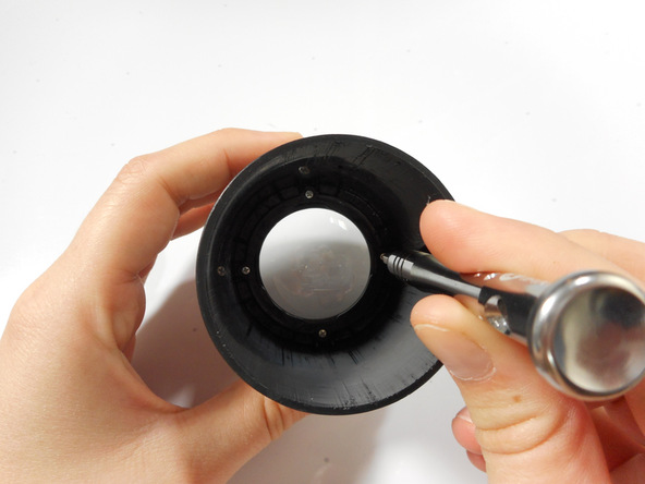
Step 9 Final Outer Lens Removal
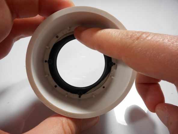
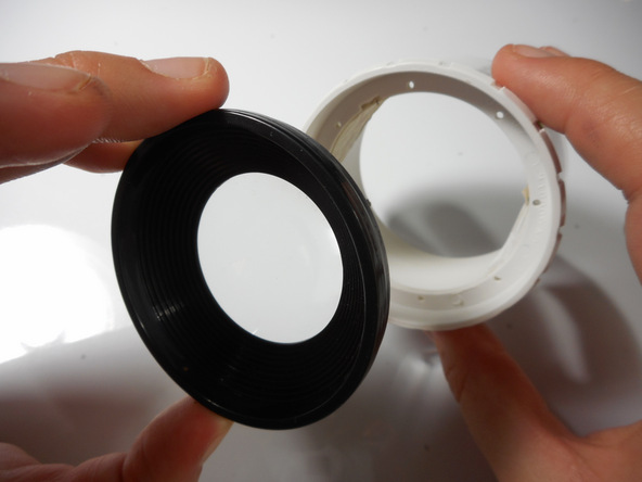
Using your finger, gently push the lens out of its white encasement.
The outer lens is now free and ready for replacement.
Merch Source Projector Entertainment II Motherboard
Introduction
Follow this guide to repair components on the logic board. All you will need a solder gun and steady hands.
Step 1 Outer Casing
Flip the projector onto its back and unscrew the nine 15mm screws using the Phillips #0 screw driver.
Flip the projector right side up and unscrew the two 12mm screws on the light bulb panel located at the rear of the projector with a Phillips #0 screw head.
The bottom right panel screw does not come completely out the panel door.
Step 3
Using your hands, gently pry the top and bottom of the projector casing apart.
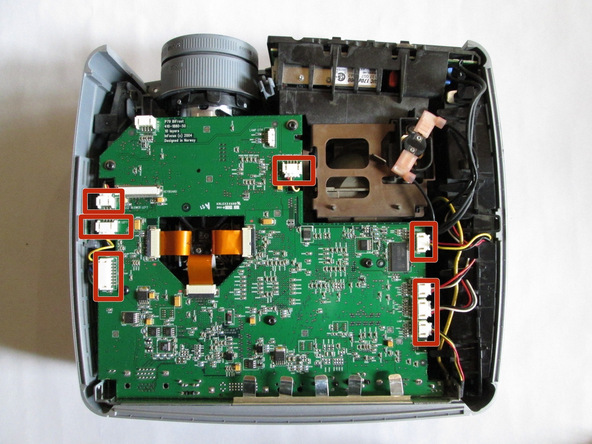
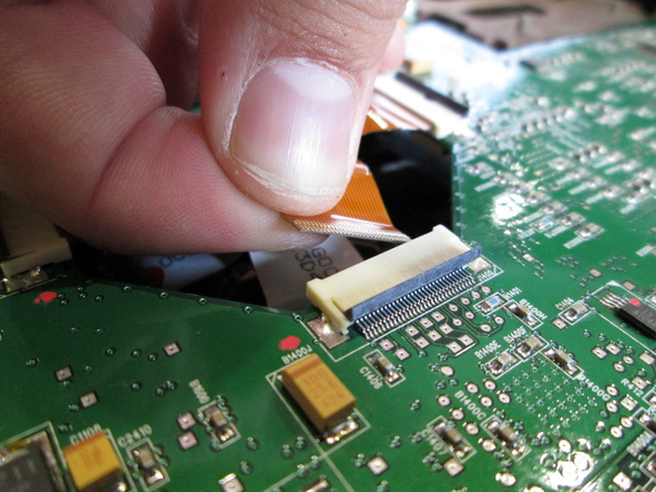
Step 4 Motherboard


Use the plastic opening tool to gently disengage the ribbon cable from its back housing.
Once the ribbon cable is disengaged gently pull the cable off the motherboard.
Once the housing is disengaged, the ribbon cable should slide out easy. Do not pull too hard on the ribbon cable as it is very fragile.


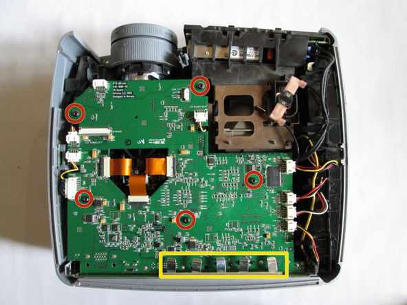
Unscrew the three 6 mm screws from the motherboard with the Phillips #0 screwdriver.
Be sure not to damage any of the wires atached to the motherboard.
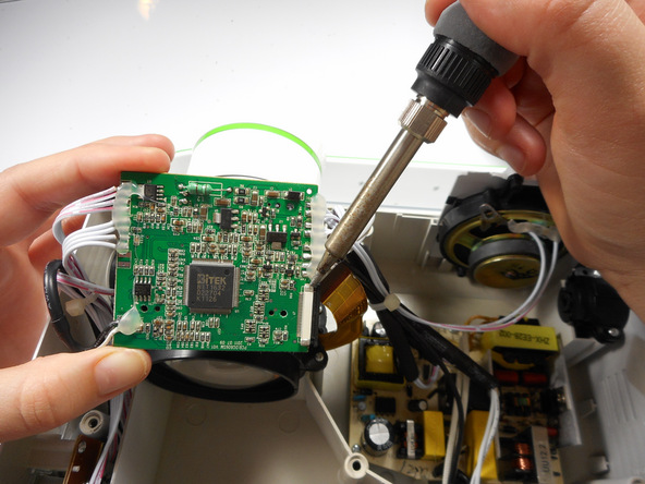
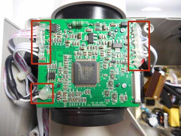
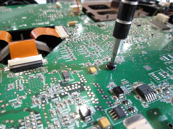
Solder off all of the connections on the motherboard with a soldering iron.
Once connections are soldered off, the motherboard should be detached and ready for replacement.
Need some help? Follow this guide to learn soldering basics.
While soldering the metal connections can get very hot. Never touch the iron with your hand. also make sure that the projector is fully turned off and not plugged in.
If there is hot glue on top on the connection with the motherboard, you will need to peel it off using your fingers.
Merch Source Projector Entertainment II Cooling Fan Replacement
Introduction
Is your projector overheating? Is it powering down at random times? Use this guide to replace the malfunctioning fan. Replacing the fan requires a fine tip soldering iron and should be done by those with solder experience.
Step 1 Outer Casing
Flip the projector onto its back and unscrew the nine 15mm screws using the Phillips #0 screw driver.
Step 2
Flip the projector right side up and unscrew the two 12mm screws on the light bulb panel located at the rear of the projector with a Phillips #0 screw head.
The bottom right panel screw does not come completely out the panel door.
Step 3
Using your hands, gently pry the top and bottom of the projector casing apart.
Step 4 Cooling Fan
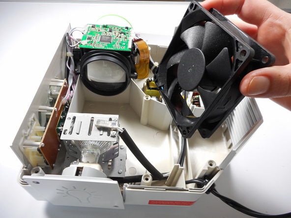
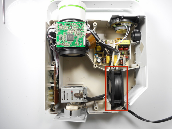
Locate the 80 mm fan and slide upward straight out of the housing.
Step 5
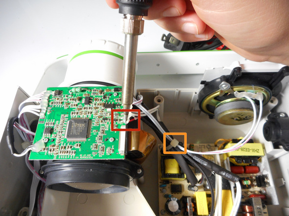
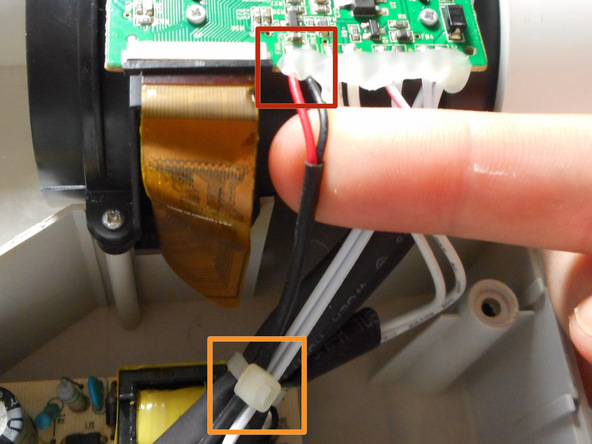
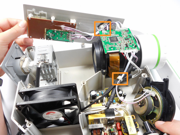
Unsolder the red and black connections off of the motherboard.
If there are zip ties around the cables, they will need to be cut to remove the fan.
Need some help? Follow this guide to learn soldering basics.
While soldering the metal connections will get very hot. Never touch the iron with your hand.
Make sure that the projector is fully turned off and not plugged in. Allow up to 30 minutes for projector to cool down.
If there is hot glue within the connection in on the motherboard, you will need to peel it off simply using your fingers.
InFocus LP540 Projector Speakers Replacement
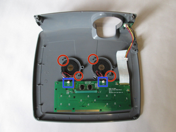
Step 1 Speakers
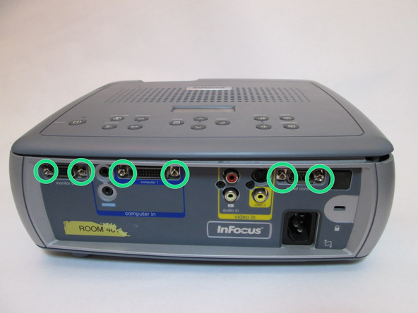


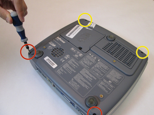
Flip the projector right-side up and turn it so that the back ports are facing you.
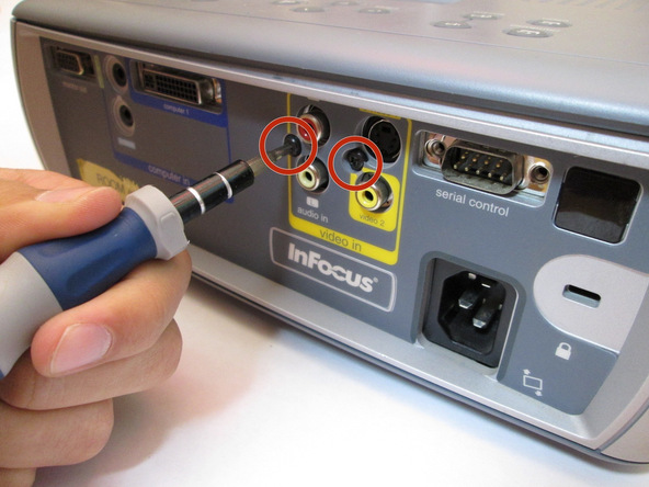
Remove the 7mm metallic hex screws using the flat-head screwdriver
Remove the two black 10mm screws using the T10 Torx screwdriver head. The screws are located at the center of the back panel.

Remove the two 77mm screws that are located nearest to the back panel ports. Use the T10 Torx screwdriver head.
Next, remove the two 10mm screws located near the lens side with the T10 Torx screwdriver head.
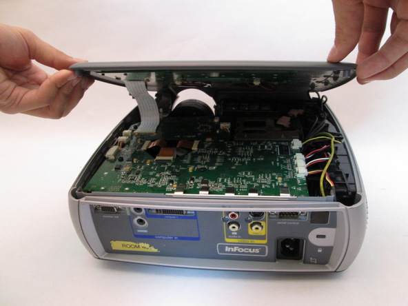
Flip the projector back over.
Then proceed to lifting up the main lid cautiously to avoid ripping the electrical strips.
Step 3

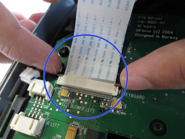
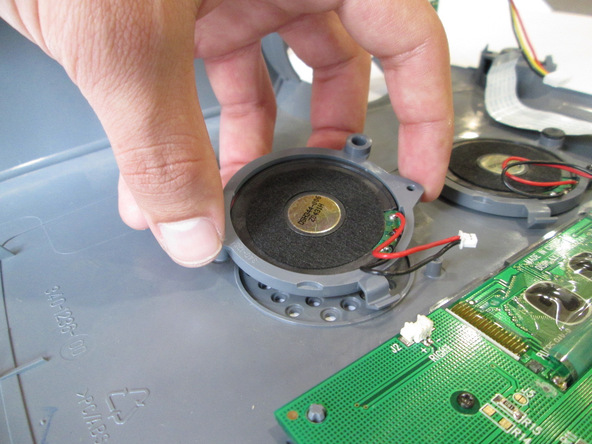
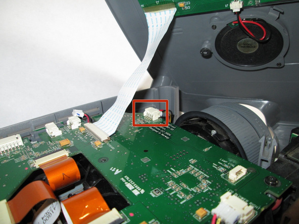
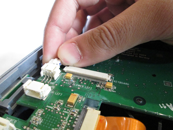
Unplug the speaker wire from the circuit board by simultaneously squeezing the sides and pulling.
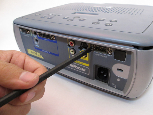
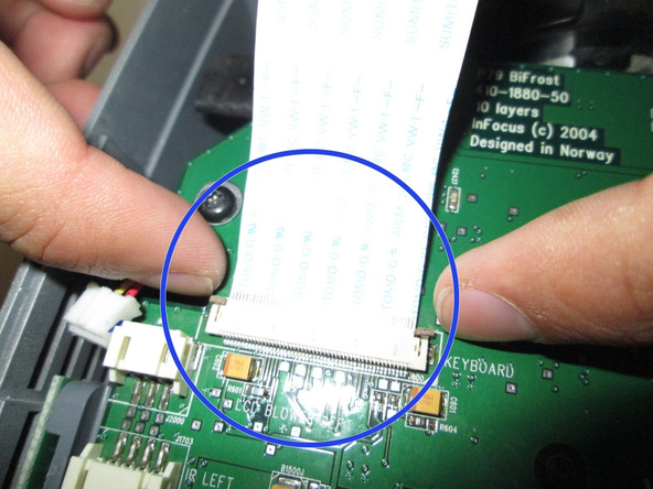
Pull on the brown tabs located at the sides of the white plastic ribbon holder and pull the ribbon out.

Place the top shell of the projector down.
Remove the speaker wires from the white tabs.
Use the Phillips 0 screwdriver to remove the four 5.5 mm screws.
Carefully lift the speakers to remove them.
InFocus LP540 Projector Lens Replacement
Step 1 Main Board

-
Flip the projector right-side up and turn it so that the back ports are facing you.
-
Remove the 7mm metallic hex screws using the flat-head screwdriver.
-
Remove the two black 10mm screws using the T10 Torx screwdriver head. The screws are located at the center of the back panel.
Step 2

-
Flip the projector over.
-
Remove the two 77mm screws that are located nearest to the back panel ports. Use the T10 Torx screwdriver head.
-
Next, remove the two 10mm screws located near the lens side with the T10 Torx screwdriver head.
-
Flip the projector back over.
-
Unplug the speaker wire from the circuit board by simultaneously squeezing the sides and pulling.
-
Pull on the brown tabs located at the sides of the white plastic ribbon holder and pull the ribbon out.
-
Pull the top cover back.
-
Remove the cables from the white tabs.
-
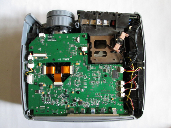
Remove the five 5mm screws located throughout the motherboard with the screwdriver. Use the T10 Torx screwdriver head.
-
Pull up on each metal tab located at the rear of the projector. There are 5 tabs.
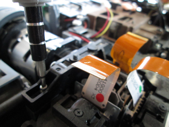
Step 6
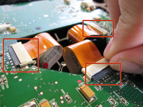
-
Remove the three gold ribbons by flipping up the black taps that hold the ribbon in place.
-
Pull the ribbons out carefully and place them under the main board.
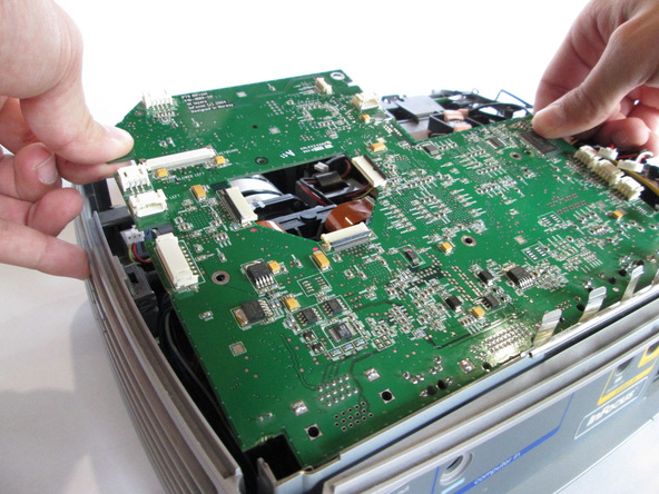
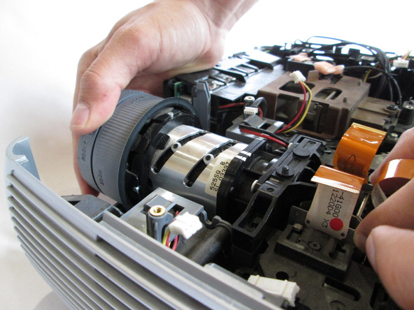
-
Carefully lift the entire main board up.
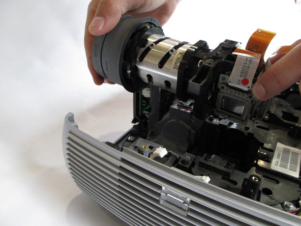
Step 7 Lens
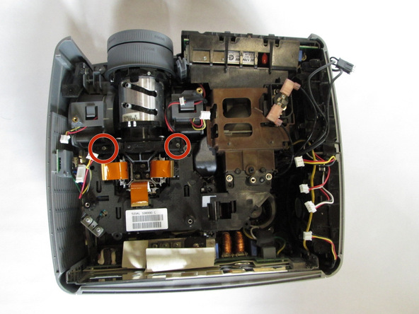
-
Remove the two 10 mm screws using the Philips 0 screwdriver head.
InFocus LP540 Projector Lamp Replacement
Introduction
This guide will assist with replacing a non-functioning projector lamp, which is responsible for providing the light necessary for projection.
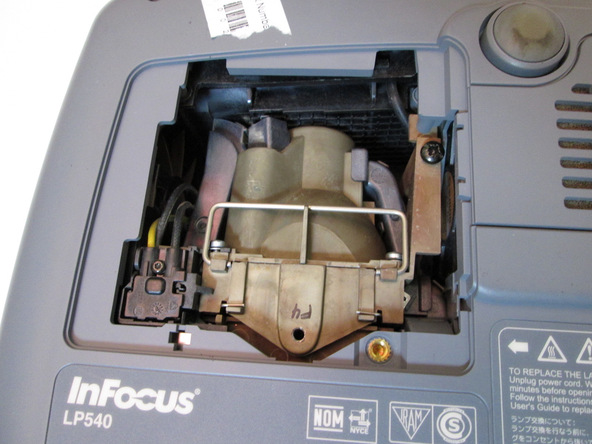
Step 1 Lamp
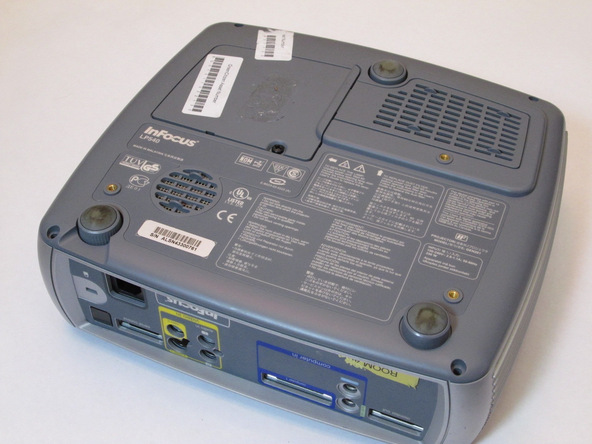
Place the projector on its back with the control buttons facing down.
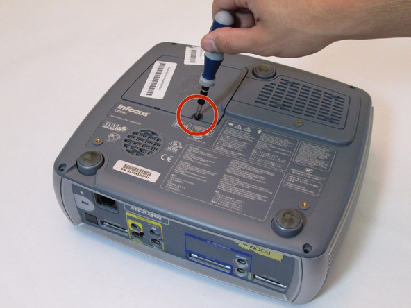
Remove the black 7mm screw on the external case with a Phillips 2 screwdriver.
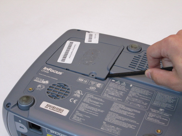
Use the plastic flat-head to remove the lamp lid.
Step 3
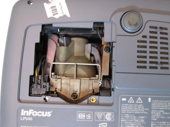
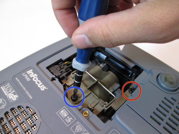
Remove the 7mm screw near the bottom center with a Philips 2 screwdriver head.
Loosen but do not remove the 7mm screw near the upper right corner with the Phillips 2 screwdriver head.
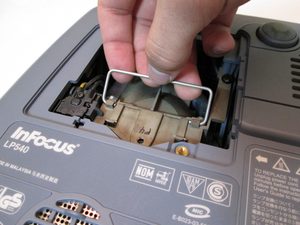

Grab the silver handle.
Unhook the handle so it can move freely.
Pull the handle straight up until the lamp is completely removed from projector.
Optoma HD20 Light Bulb Replacement
Introduction
Use this guide to remove the light bulb from your Optoma HD20.
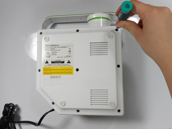
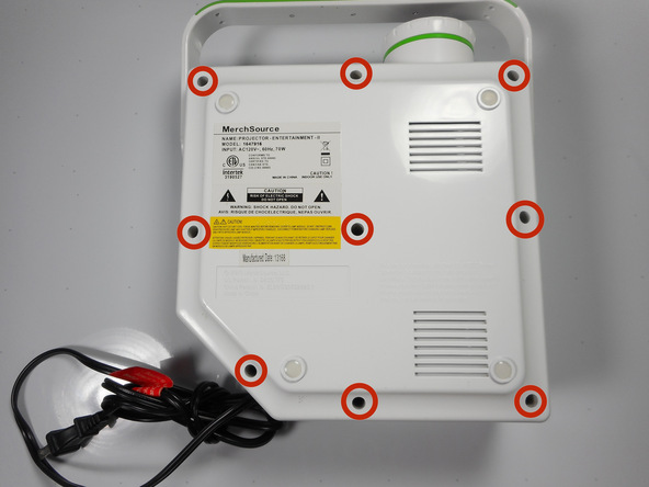
Step 1 Rear Panel
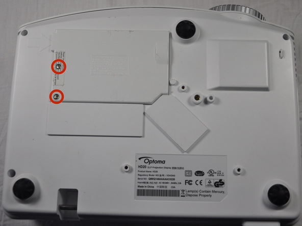
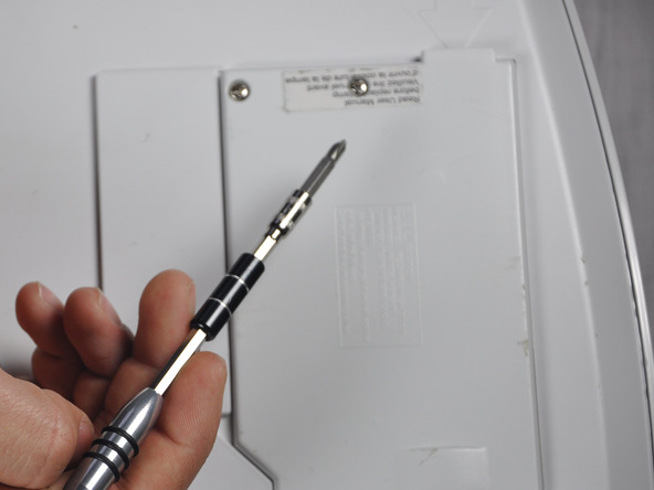
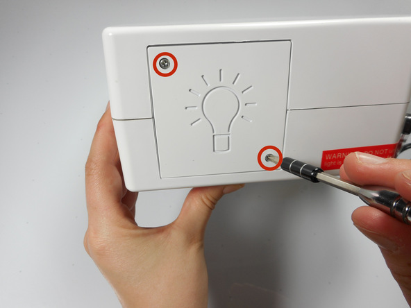
Use a Phillips #1 screwdriver to loosen the screws circled on the bottom of the device.
Screws don’t remove completely, only come out 5 mm.
Step 2
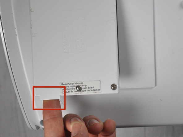
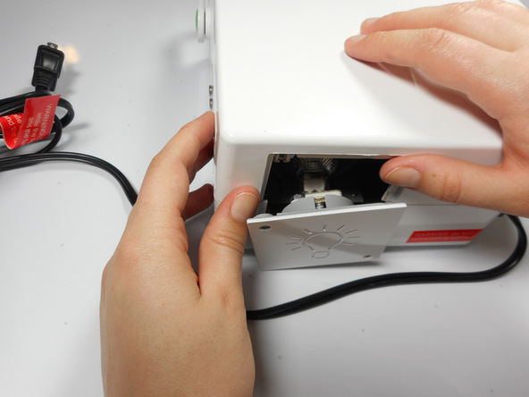
Lift panel off device.
Step 3 Light Bulb Casing
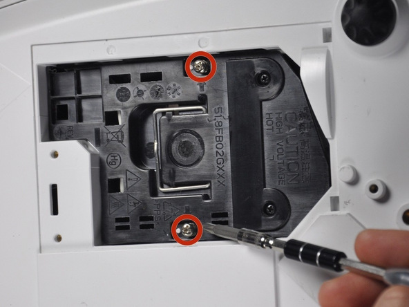
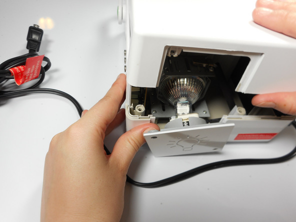
Loosen the two screws holding the black casing down with a Phillips #1 screwdriver.
Screws do not remove from black casing
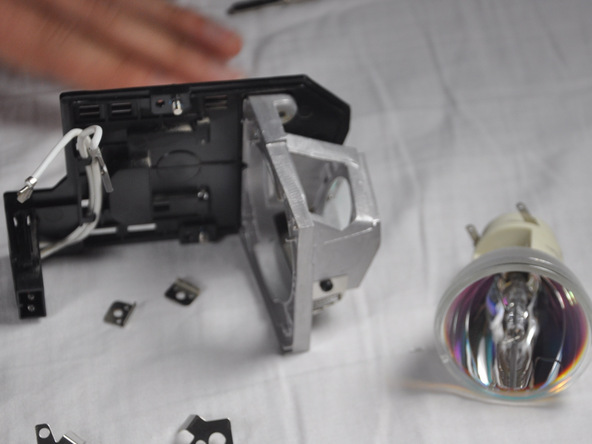
Step 4
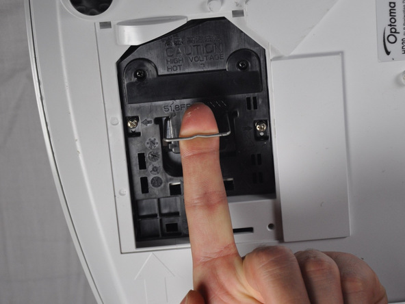
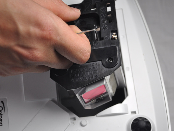
Once the screws are loosened pull out light bulb casing.
Steps 5-9 may be unnecessary if replacement light bulb comes with housing.
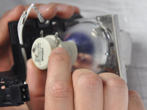
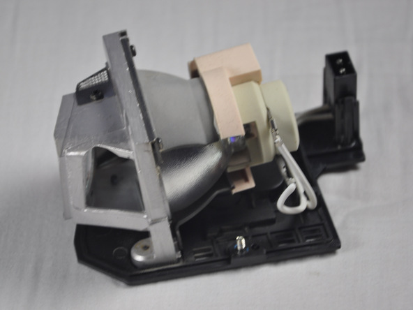
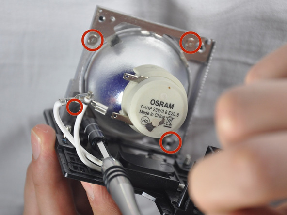
Step 5 Light Bulb
Remove the three 4.5 mm screws on the light bulb case.
Carefully pull out the light bulb insulator once the screws have been removed so you do not break it.
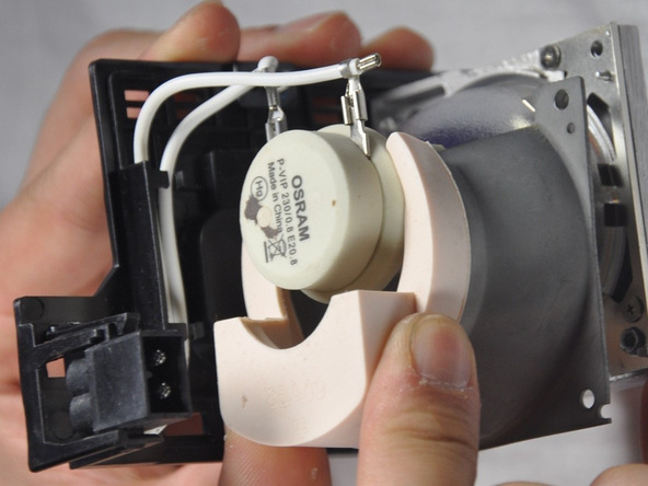
Step 7
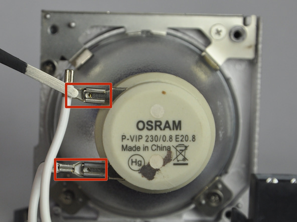
Gently pull the wires off the pins using metal tweezers.
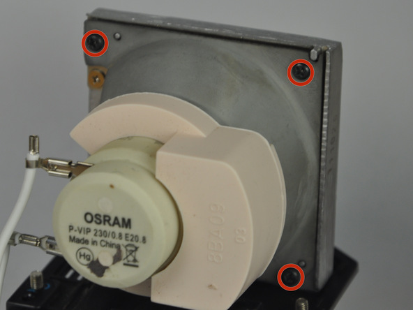
Step 8
Remove the 4 screws using a Phillips #1 screwdriver to remove the final casing around the bulb.
Step 9