


تعمیر ویدئو پروژکتور های LCD

تعمیر ویدئو پروژکتور
PANASONIC –NEC – SONY – OPTOMA – EPSON – PROXIMA – SHARP – HITACHI – ACER – TOSHIBA
سرویس و تعمیر تخصصی انواع دستگاه های ویدئو پروژکتور
جنرال سرویس و رفع ایراد های تخصصی، تشخیص و تعویض قطعه
لامپ ویدئو پروژکتور، لامپ بلاست، تراشهDMD، چرخه رنگ، ال سی دی، منبع تغذیه، فن، MAIN BOARD
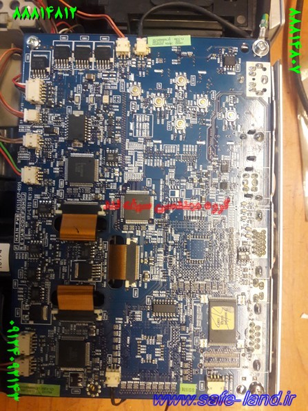
تعمیر تخصصی برد الکترونیکی انواع ویدئوپروژکتور
تعمیر ویدئو پروژکتور های LCD
تعمیر ویدئو پروژکتور های LCD
تعمیر ویدئو پروژکتور
PANASONIC –NEC – SONY – OPTOMA – EPSON – PROXIMA – SHARP – HITACHI – ACER – TOSHIBA
سرویس و تعمیر تخصصی انواع دستگاه های ویدئو پروژکتور
جنرال سرویس و رفع ایراد های تخصصی، تشخیص و تعویض قطعه
لامپ ویدئو پروژکتور، لامپ بلاست، تراشهDMD، چرخه رنگ، ال سی دی، منبع تغذیه، فن، MAIN BOARD
تعمیر تخصصی برد الکترونیکی انواع ویدئوپروژکتور
Do you have a projector that’s a bit poorly
Do you have a projector that’s a bit poorly? Perhaps it has stopped working altogether or works but it is displaying strange colors on the image? Alternatively it could be making funny noises or working but not displaying an image? Whatever the problem, our projector repair team can fix it!
UK Projector Services offer the total after care solution, so we ensure that you get the most from the audio visual equipment you purchase. Excellent turnaround times to ensure that your projector is back working with the minimum of disruption.
We offer full repair and servicing facilities on all LCD,DLP, video, home theatre projectors.
As with any expensive equipment, you want to send it to someone who knows what they are doing. We have a minimum of 20 years experience in the repair industry and there is not much that we have not ever seen.
We will diagnose the problem for you as soon as we can and supply you with a repair estimate for the work that would need to be done. Why not get a FREE quote to discuss your problem, often we can diagnosis it over the telephone and advise you the best course of action, either send the projector in for repair, or buy a new lamp.
نمونه
How to Fix a Faulty LCD Projector
How to Fix a Faulty LCD Projector


Many people and companies are using LCD projectors nowadays. In different universities, classes use LCD projectors in discussions and the same for business meetings and presentations as they are used by many corporations. People now also use the projectors as part of their home entertainment systems.
What is an LCD Projector?
LCD projector refers to a kind of video projector that is used to display or “project” an image, video, and computer data on a flat exterior or simply a screen. In order to project images and other similar presentations, light is projected from the Metal halide lamp to a prism placed in between the three poly silicone panels. Despite the advancement of an LCD projector, there are times that it simply malfunctions. There are different kinds of LDC problems and for every faulty LCD projector, there is a corresponding solution.
Materials Needed
Basically, the main thing to do in fixing a faulty projector is to test and then replace or change the specifications. For image distortions, it’s the setting of the projector and the computer that should be changed. For faulty images the following might be needed:
Screwdriver
Lamp replacement
Mirror replacement
Pliers or tweezers
Fixing LCD Projector that do not Display Computer Images
If the projector shows DVD, CCTV, and VHS but will not project the image from the computer, the following steps should be done.
Using the manual from the manufacturer, check the computer’s refresh rate. Adjust the settings of the refresh rate.
Go to start, click Control Panel then proceed to Appearance and Themes then go to Display.
Go to Settings Tab then proceed to the Advanced Option. There should be the Monitor options.
Checking the refresh rate in the manual of the projector, adjust the settings accordingly.
Repairing Projector with Yellowish Image
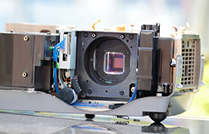
Step 1: Check the LCD Panel
A yellow image from the projector is usually the result of a broken LCD panel. To see which panel is broken, pop the cover of the projector using the screwdriver. Make sure to refer first to the manual before opening the projector. Inside the projector, mirrors are positioned to separate each colored LCD panel: red, blue and green. The panels are placed around a prism that mixes the three colors together to display an image.
Step 2: Test Each LCD Panel
In order to test each panel, the projector has to be turned on. Make sure that no sensitive parts are touched to avoid problems. Cover each panel with a paper or cardboard and see which panel does not reflect the color well. The malfunctioning panel will not be able to respond to a signal. It will also show which panel does not reflect the right form of the image.
Step 3: Replace the Malfunctioning Part
Using pliers or tweezers, take out the malfunctioning panel. This step may not be applicable to all projectors so check with the manual how to detach the panels. Once the malfunction part is taken out, position the replacement.
Step 4: Check the Panels Again
Check the panel by shielding it again. See if it already reflects the right color and the correct image quality.
Step 5: Cover the Projector
Screw on the lid and test the projector.
Merch Source Projector Entertainment II Speaker Replacement
Introduction
Muffled sound? Distorted sound? No sound? No problem! Simply use this guide to regain awesome audio in your projector. To follow this guide, you should have the following parts handy:
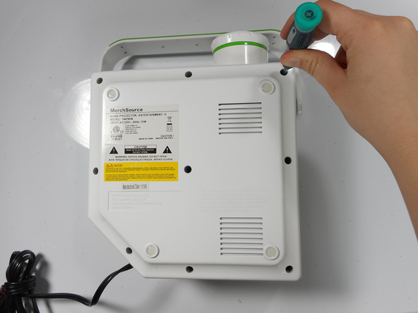
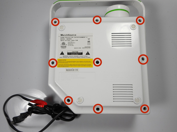
Step 1 Outer Casing
-
Flip the projector onto its back and unscrew the nine 15mm screws using the Phillips #0 screw driver.
Step 2
-
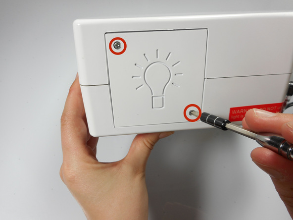
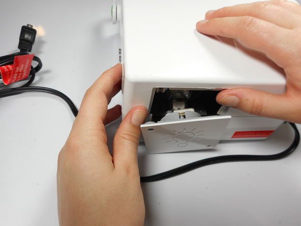
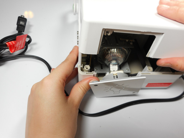
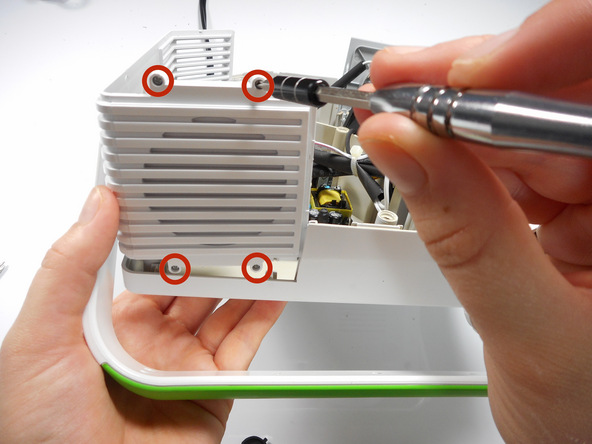
Flip the projector right side up and unscrew the two 12mm screws on the light bulb panel located at the rear of the projector with a Phillips #0 screw head.
Step 3
-
Using your hands, gently pry the top and bottom of the projector casing apart.
Step 4 Speaker

-
Locate the 2 screws on the handle casing. These screws are mirrored on the handle attachment on the other side panel as well.
-
Unscrew the two 16mm screws using the Phillips #0 screw driver. Repeat for the opposite side panel.
Step 5
-
Lift up on the side panel and speaker attachment to slightly dislodge it.
-
Unscrew the four 9mm Phillips screws with a Phillips #0 screw driver, located on the outside of the projector casing.
Step 6
-
Once the side panel door has been lifted out of the bottom casing, it can swing freely.
-
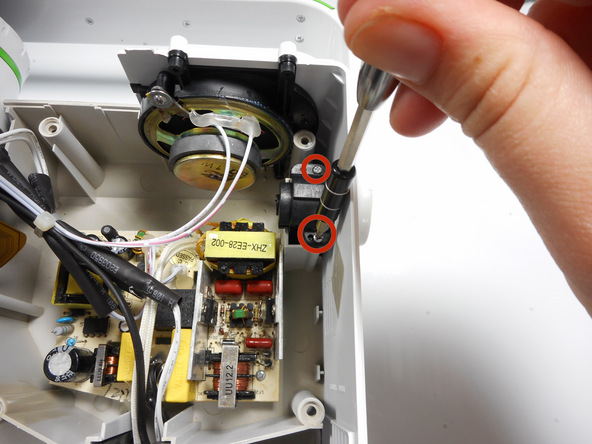
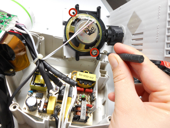
Rotate the side panel door forward so that you can access the screws on the speaker.
-
Unscrew the two 10mm screws with a Phillips #0 screw driver.
-
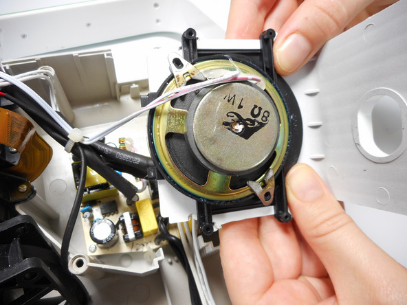
Lift the side panel and speaker out from the projector casing.
-
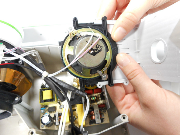
Using your hands, slide the speaker outward from the side panel.
Step 8
Edit
![Image 2/3: Need some help? Follow this [guide|750|guide] to learn soldering basics.](http://safe-land.ir/wp-content/uploads/2016/12/HALXlXV5KKunfIHf.medium)
-
Locate the two speaker wires connected to the sound and audio motherboard on the left panel opposite of the speaker. Unsolder these connections with a soldering iron.
-
Once the wires are disconnected, in order to fully remove the speaker you may need to cut the plastic bands holding the speaker wires in place.
Merch Source Projector Entertainment II Outer Lens Replacement
Introduction
Do you have a blurry image or a broken outer lens? Follow these step by step instructions to learn how to disassemble the projector and remove the outer lens for your repairs.
Step 1 Outer Casing
Flip the projector onto its back and unscrew the nine 15mm screws using the Phillips #0 screw driver.
Step 2
Flip the projector right side up and unscrew the two 12mm screws on the light bulb panel located at the rear of the projector with a Phillips #0 screw head.
The bottom right panel screw does not come completely out the panel door.
Step 3
Using your hands, gently pry the top and bottom of the projector casing apart.
Step 4 Ribbon Cable Detachment
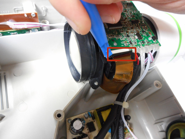
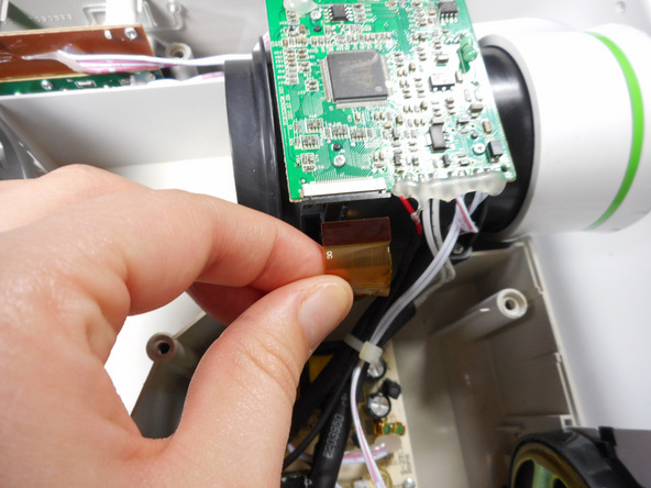
Use the plastic opening tool to gently disengage the black clip housing from the ribbon cable.
Once the ribbon cable is disengaged gently pull the cable off the motherboard.
Once the housing is disengaged, the ribbon cable should slide out easily. Do not pull too hard on the ribbon cable as it is very fragile.
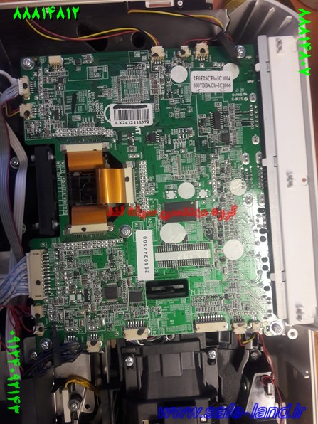
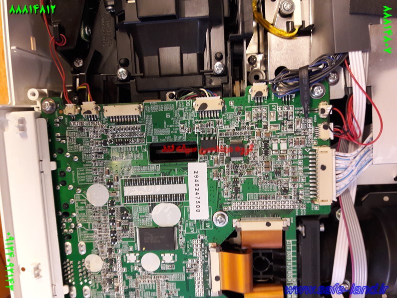
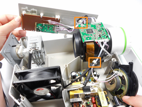
Step 5 Motherboard Detachment
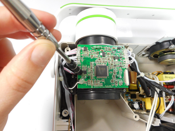
Unscrew the three 7 mm screws from the motherboard with the Phillips #0 screw driver.
Once loose, lift the motherboard off of the lens casing, and move it away from the workspace.
Be sure not to damage any of the wires atached to the motherboard.
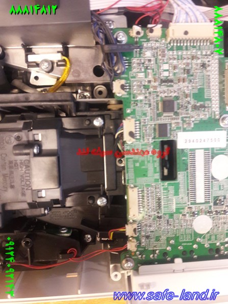
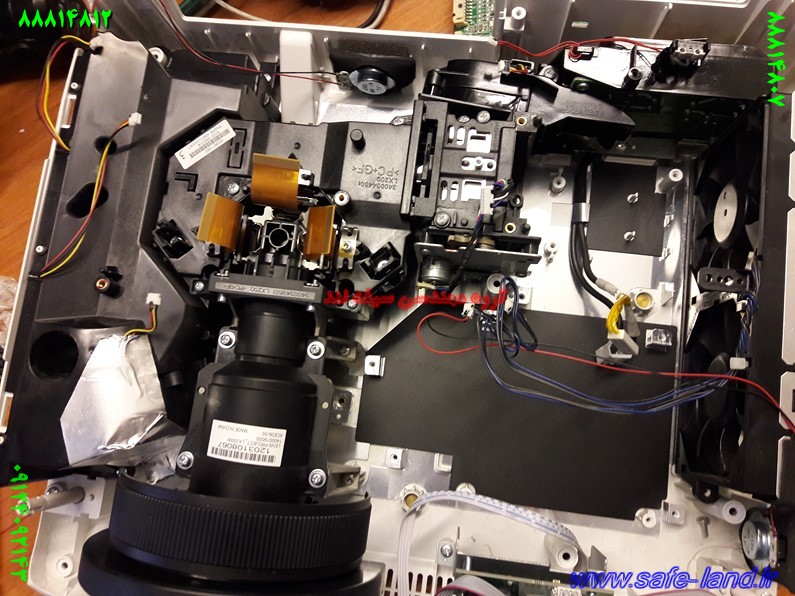
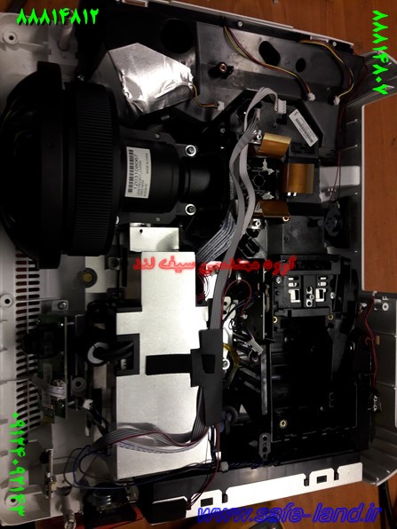
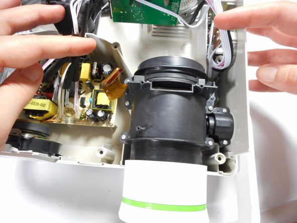
Step 6 Lens Casing Detachment
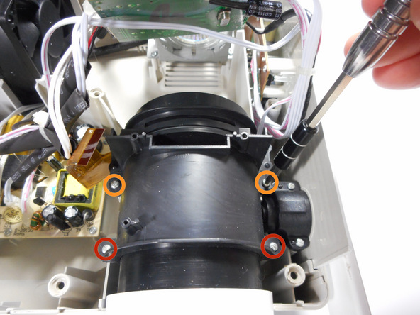
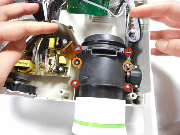
Unscrew the four 15mm Phillips screws using the Phillips #0 screw driver.
Unscrew the two 12mm Phillips screws using the Phillips #0 screw driver.
Gently remove the entire lens casing from it’s position.
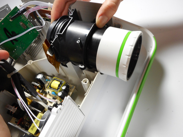
Step 7 Lens Casing Seperation
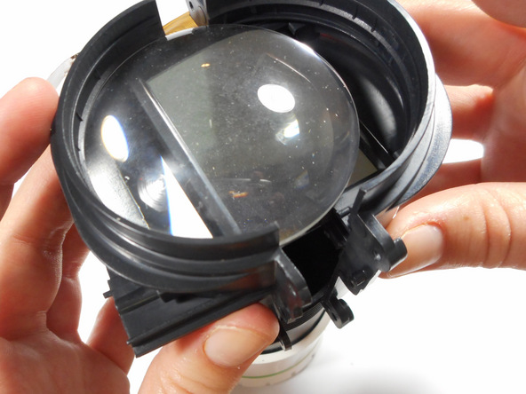
Using the plastic opening tool, slightly separate the casing holding the large lens in place.
Separate the casing completely from the inner lens using your hands.
This should release the outer lens and it’s immediate casing.
As you separate the outer casing, the lens and digital display box may fall out of their encasement.
Although there are threads connecting the outer lens casing and the inner lens casing, do not be fooled. The outer lens casing cannot be disconnected by unscrewing it.
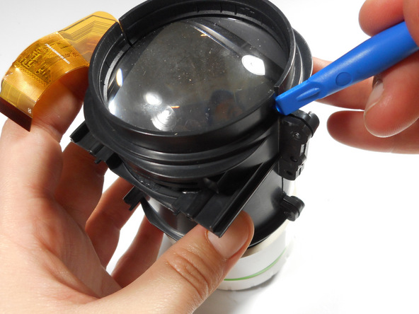
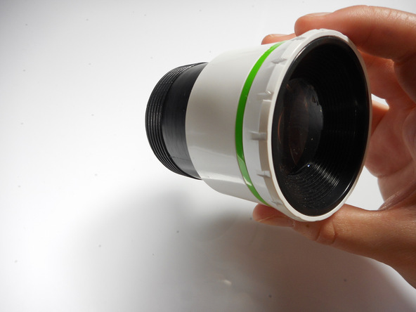
Step 8 Outer Lens Casing Seperation
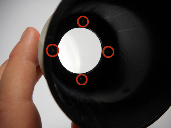
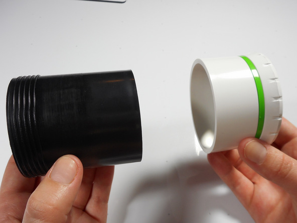
Unscrew the four 8mm Phillips screws at the base of the outer lens casing using the Phillips #0 screw driver.
Separate the white outer casing from the black outer casing.
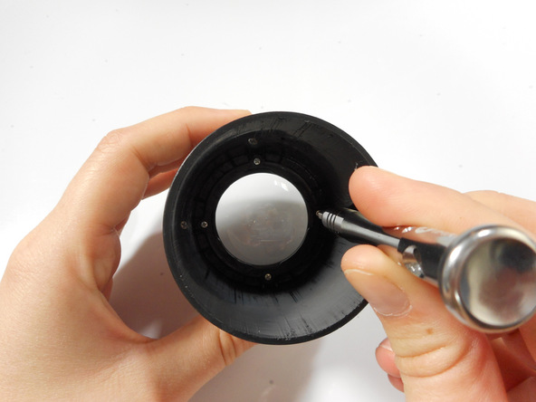
Step 9 Final Outer Lens Removal
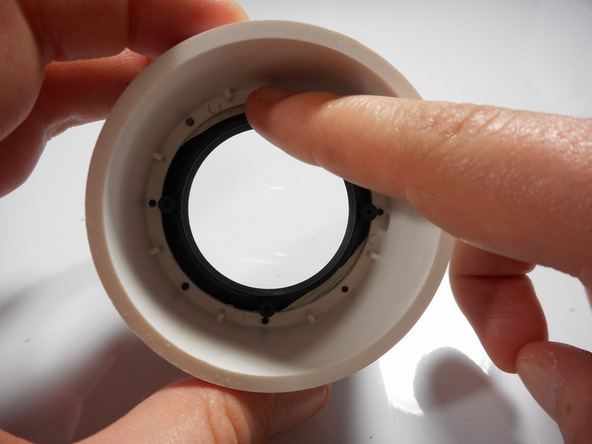
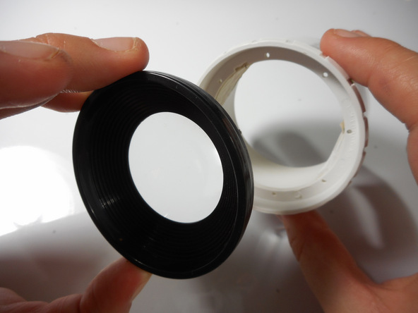
Using your finger, gently push the lens out of its white encasement.
The outer lens is now free and ready for replacement.
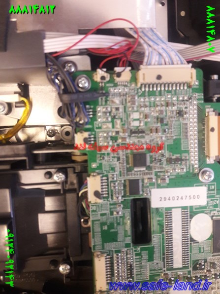
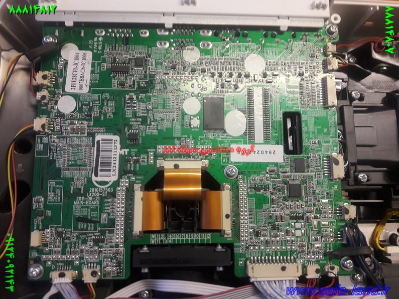
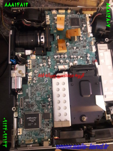
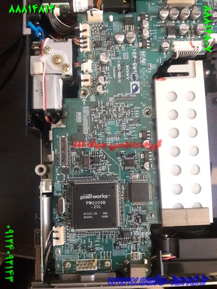
Merch Source Projector Entertainment II Motherboard
Introduction
Follow this guide to repair components on the logic board. All you will need a solder gun and steady hands.
Step 1 Outer Casing
Flip the projector onto its back and unscrew the nine 15mm screws using the Phillips #0 screw driver.
Flip the projector right side up and unscrew the two 12mm screws on the light bulb panel located at the rear of the projector with a Phillips #0 screw head.
The bottom right panel screw does not come completely out the panel door.
Step 3
Using your hands, gently pry the top and bottom of the projector casing apart.
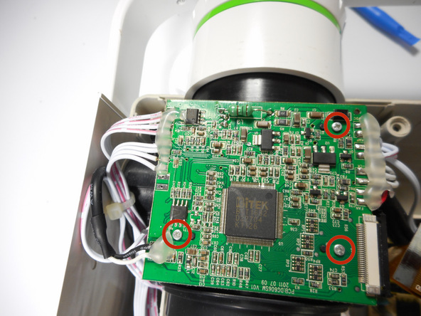
Step 4 Motherboard


Use the plastic opening tool to gently disengage the ribbon cable from its back housing.
Once the ribbon cable is disengaged gently pull the cable off the motherboard.
Once the housing is disengaged, the ribbon cable should slide out easy. Do not pull too hard on the ribbon cable as it is very fragile.


Unscrew the three 6 mm screws from the motherboard with the Phillips #0 screwdriver.
Be sure not to damage any of the wires atached to the motherboard.
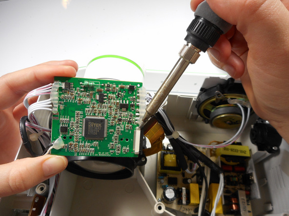
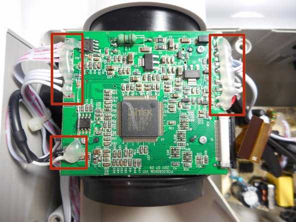
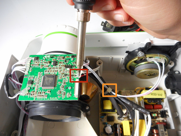
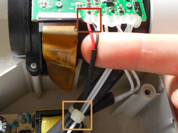
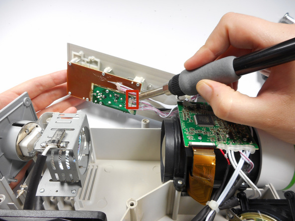
Solder off all of the connections on the motherboard with a soldering iron.
Once connections are soldered off, the motherboard should be detached and ready for replacement.
Need some help? Follow this guide to learn soldering basics.
While soldering the metal connections can get very hot. Never touch the iron with your hand. also make sure that the projector is fully turned off and not plugged in.
If there is hot glue on top on the connection with the motherboard, you will need to peel it off using your fingers.
Merch Source Projector Entertainment II Cooling Fan Replacement
Introduction
Is your projector overheating? Is it powering down at random times? Use this guide to replace the malfunctioning fan. Replacing the fan requires a fine tip soldering iron and should be done by those with solder experience.
Step 1 Outer Casing
Flip the projector onto its back and unscrew the nine 15mm screws using the Phillips #0 screw driver.
Step 2
Flip the projector right side up and unscrew the two 12mm screws on the light bulb panel located at the rear of the projector with a Phillips #0 screw head.
The bottom right panel screw does not come completely out the panel door.
Step 3
Using your hands, gently pry the top and bottom of the projector casing apart.
Step 4 Cooling Fan
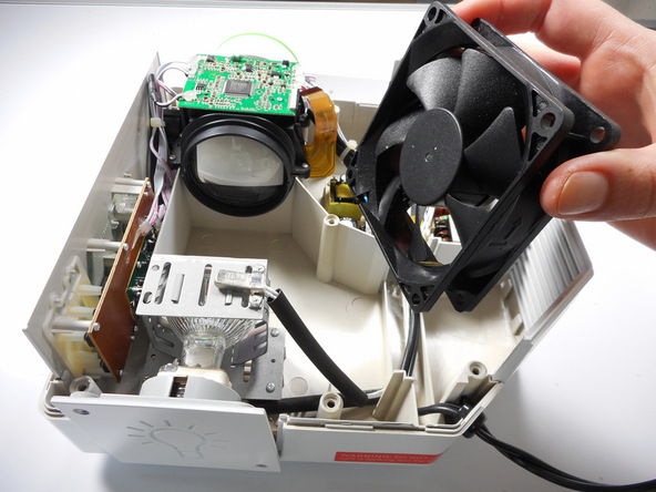
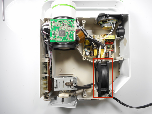
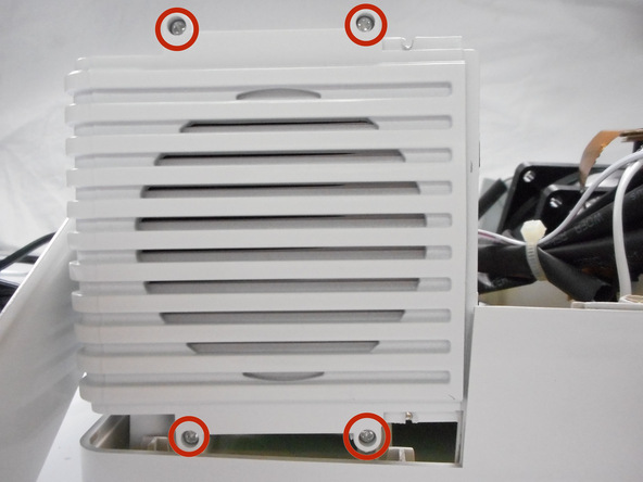
Locate the 80 mm fan and slide upward straight out of the housing.
Step 5