Introduction
Use this guide to remove the light bulb from your Optoma HD20.
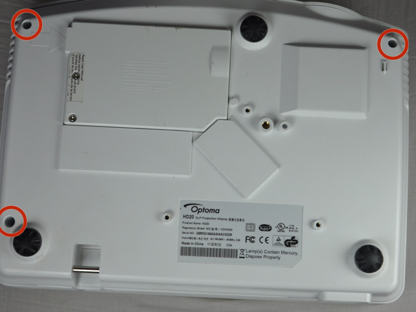
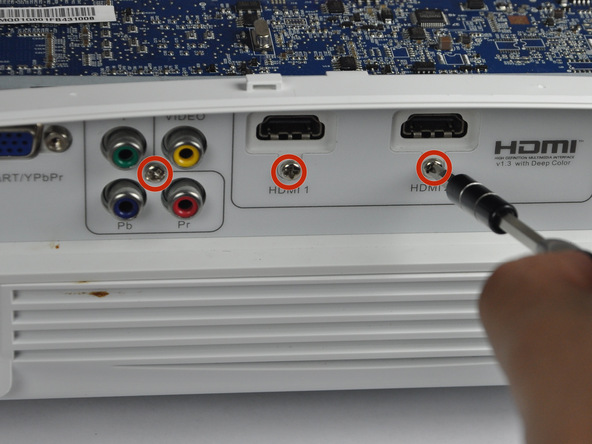
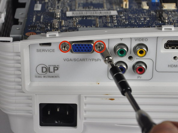
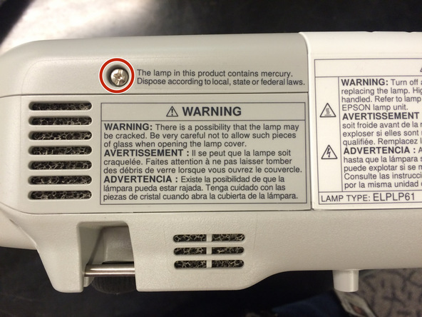
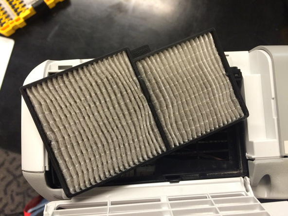
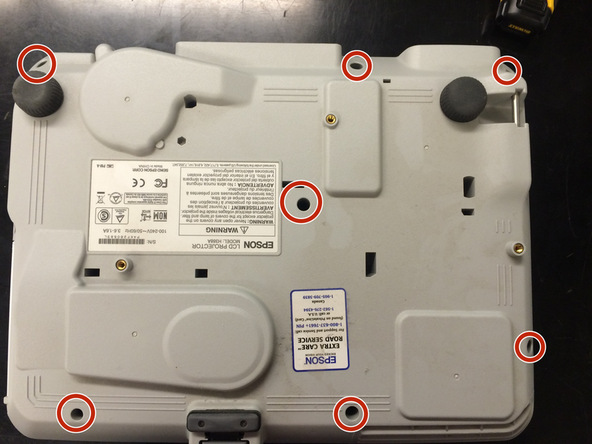
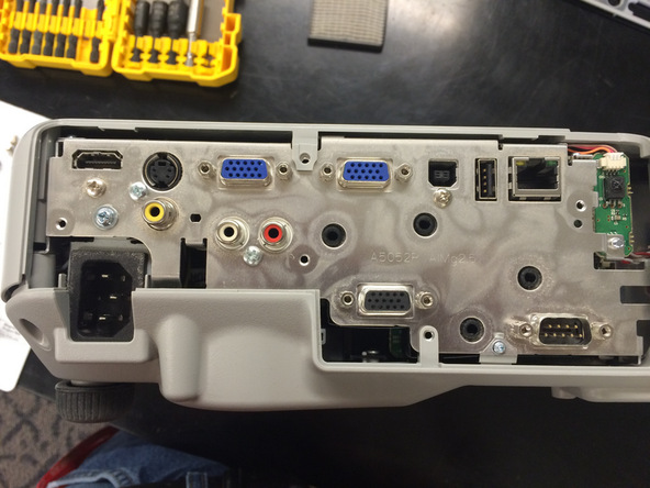
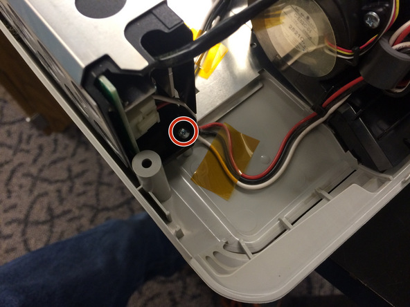
Step 1 Rear Panel
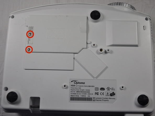
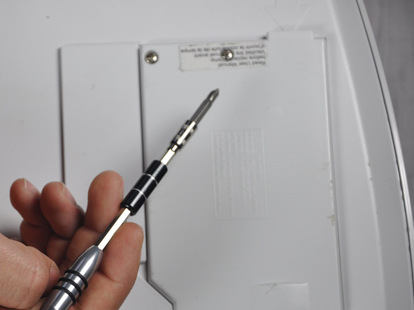
Use a Phillips #1 screwdriver to loosen the screws circled on the bottom of the device.
Screws don’t remove completely, only come out 5 mm.
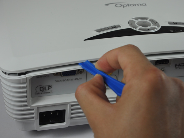
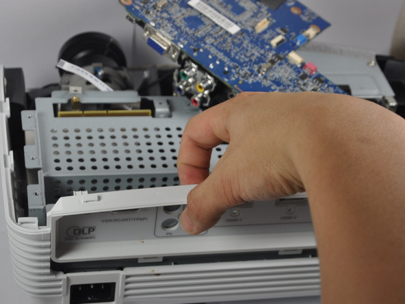
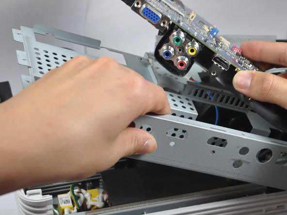
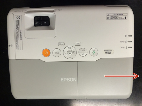
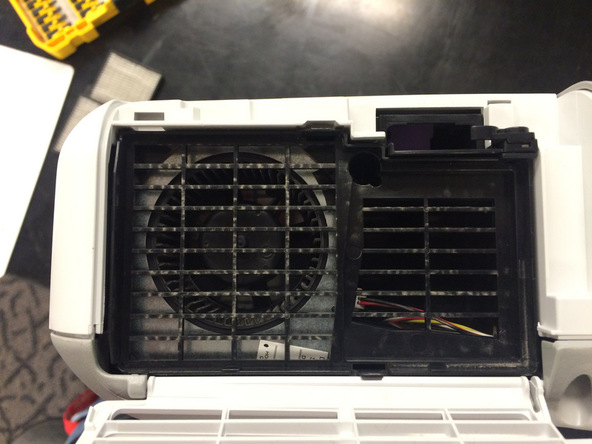
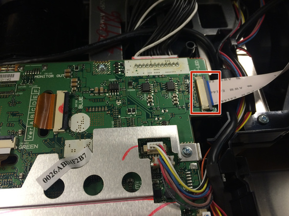
Step 2
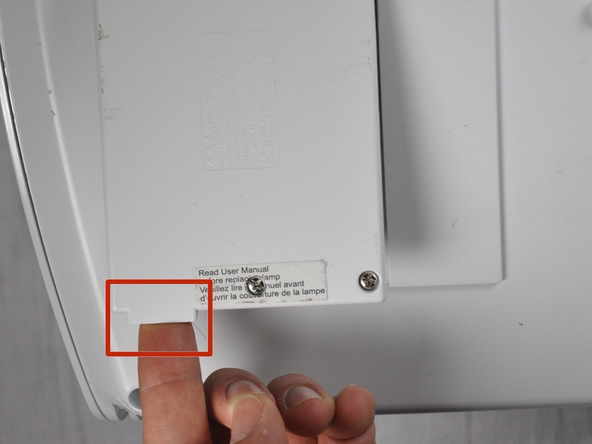
Lift panel off device.
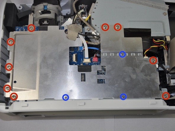
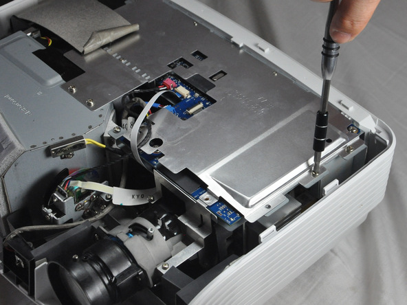
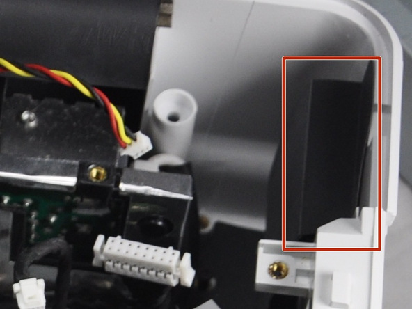
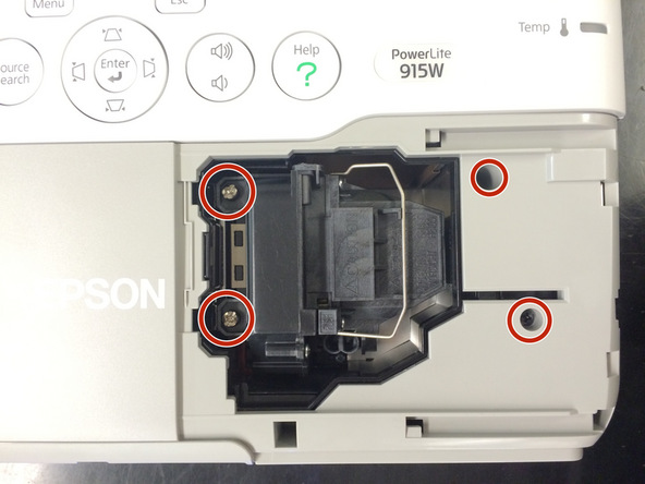
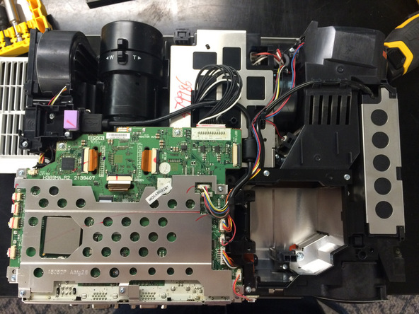
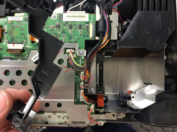
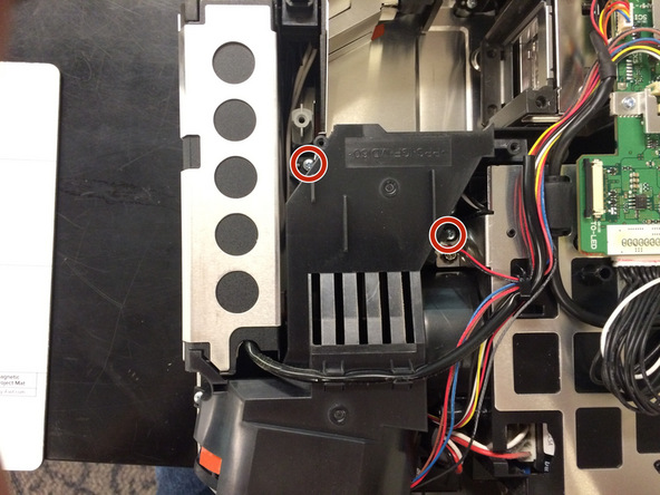
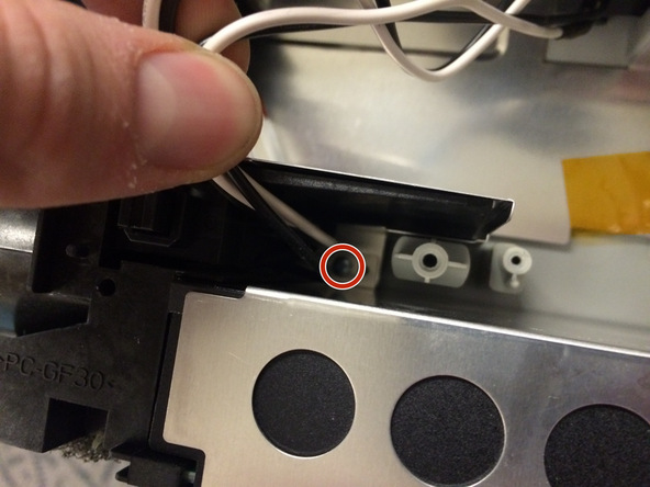
Step 3 Light Bulb Casing
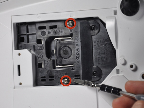
Loosen the two screws holding the black casing down with a Phillips #1 screwdriver.
Screws do not remove from black casing
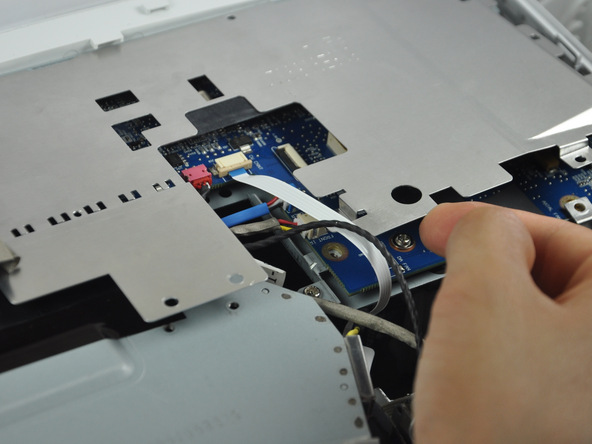
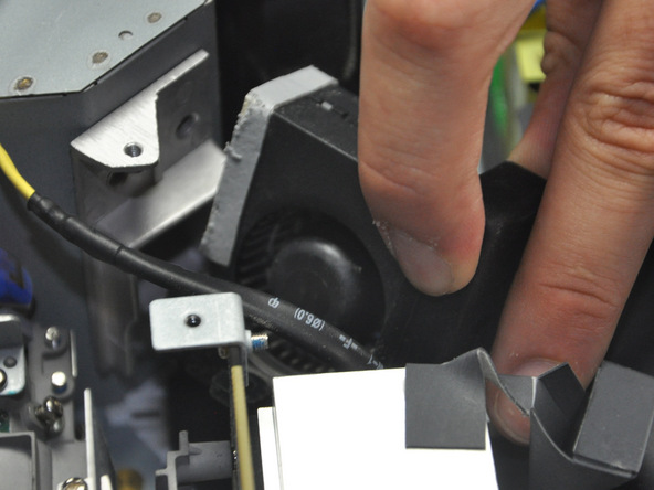
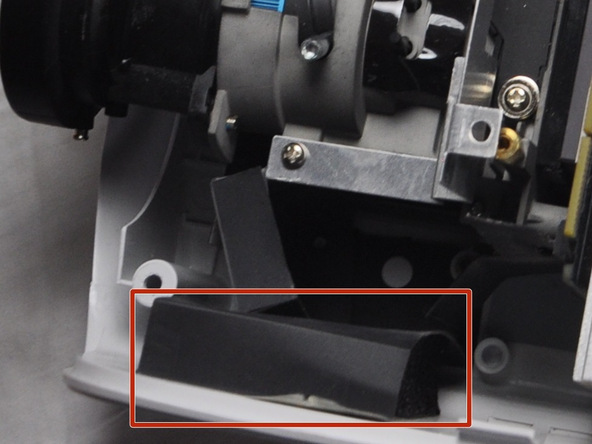
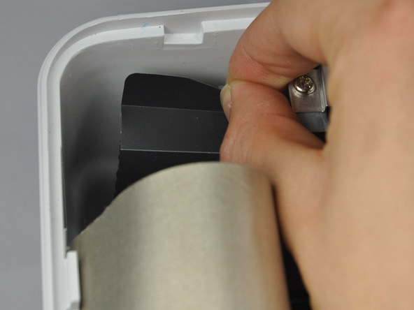
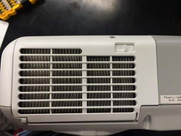
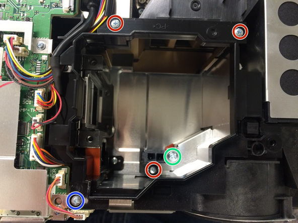
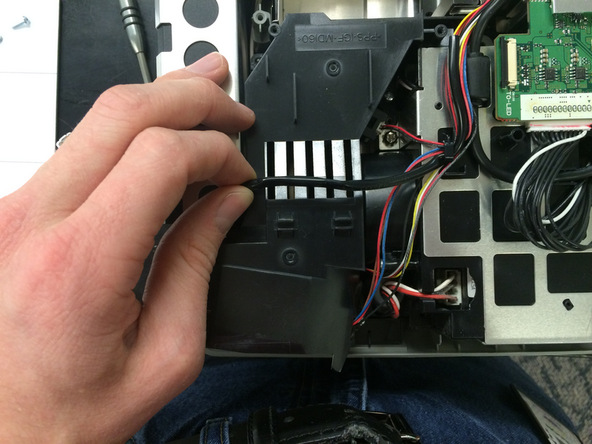
Step 4
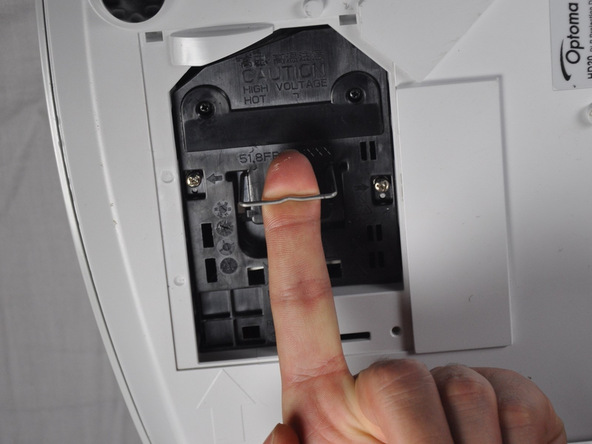
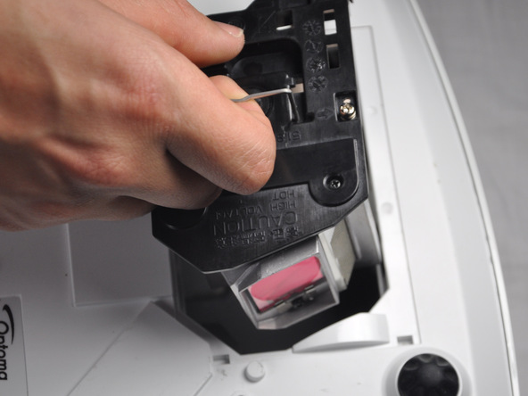
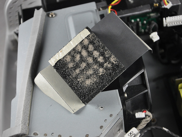
Once the screws are loosened pull out light bulb casing.
Steps 5-9 may be unnecessary if replacement light bulb comes with housing.
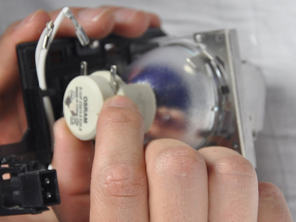
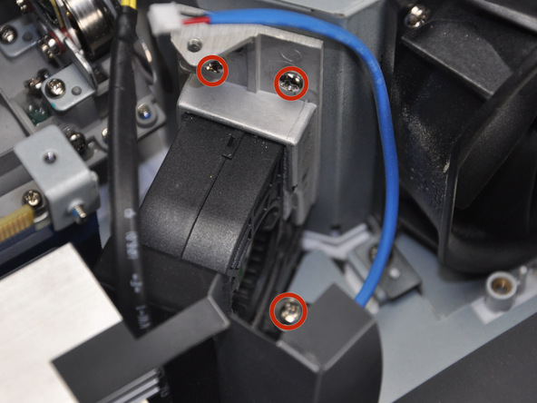
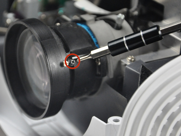
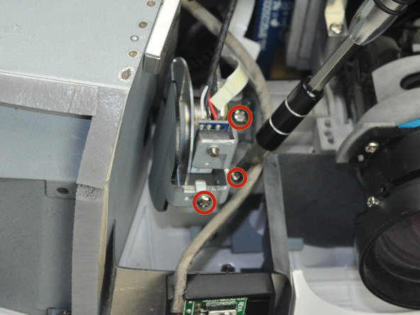
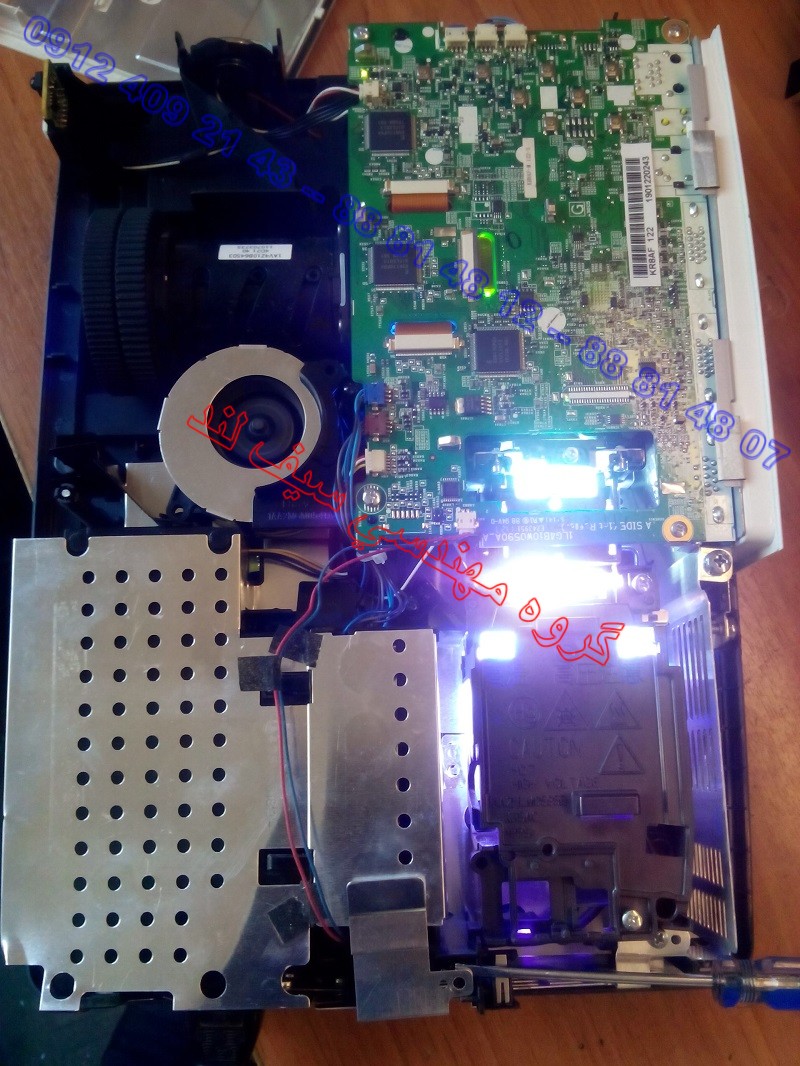
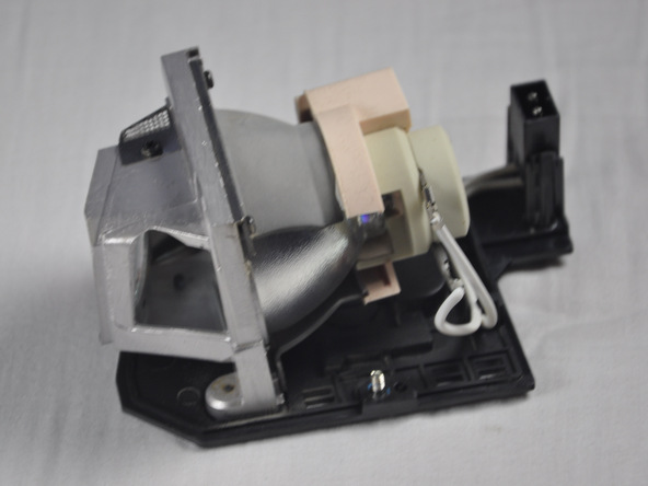
Step 5 Light Bulb
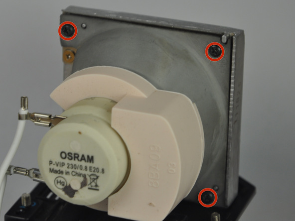
Remove the three 4.5 mm screws on the light bulb case.
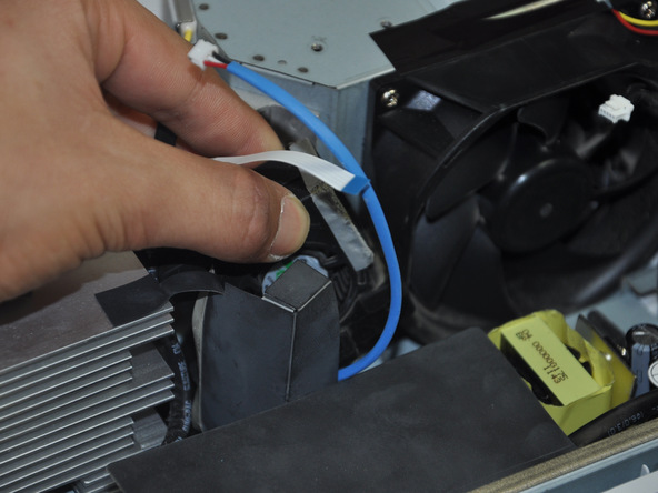
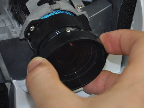
Carefully pull out the light bulb insulator once the screws have been removed so you do not break it.
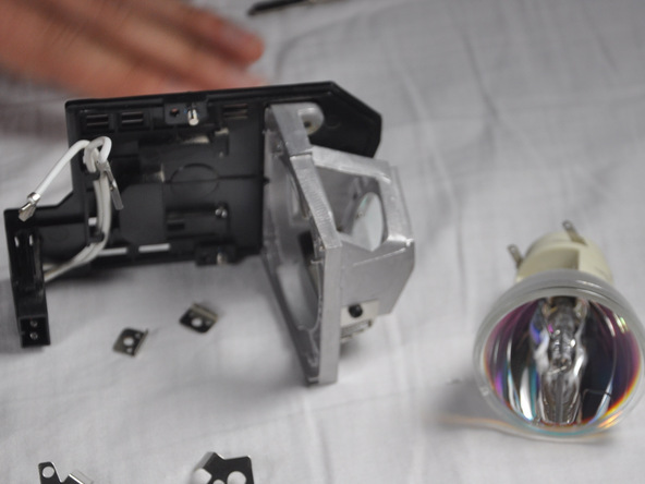
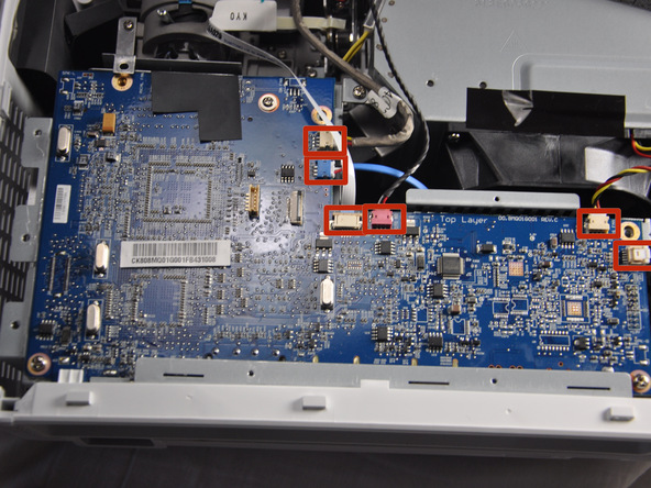
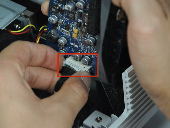
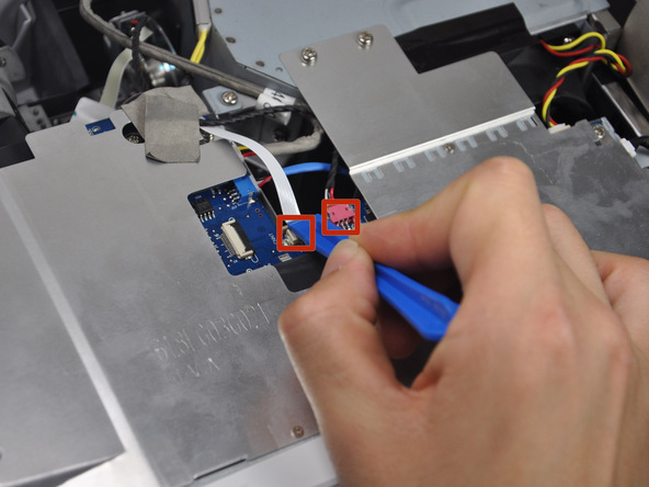
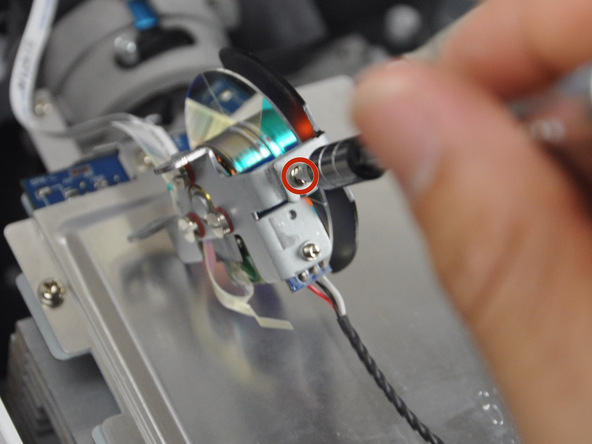
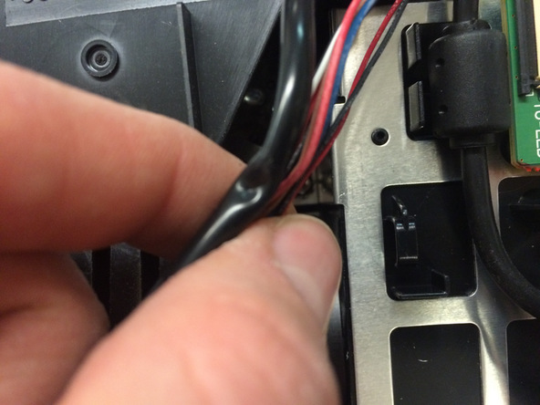
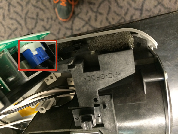
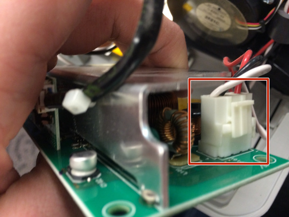
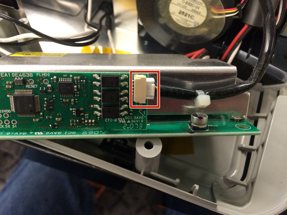
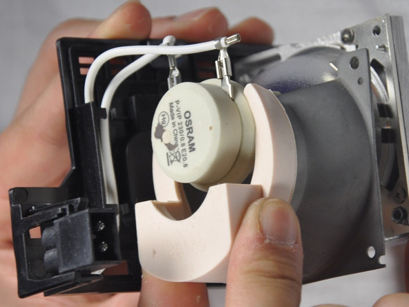
Step 7
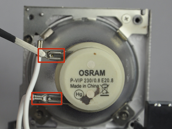
Gently pull the wires off the pins using metal tweezers.
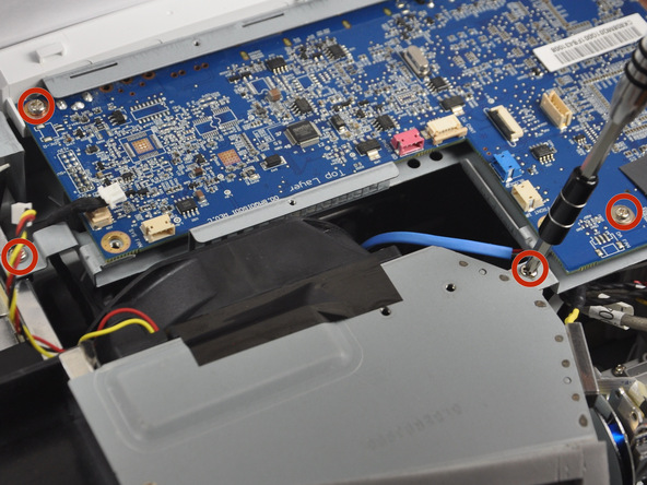
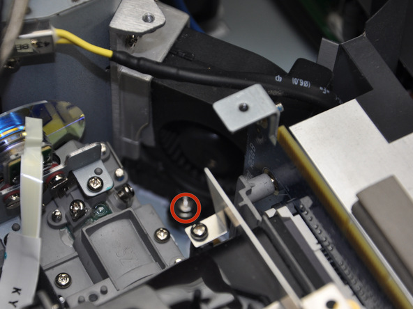
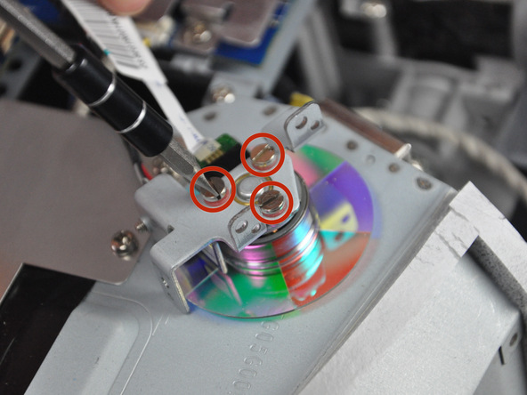
Step 8
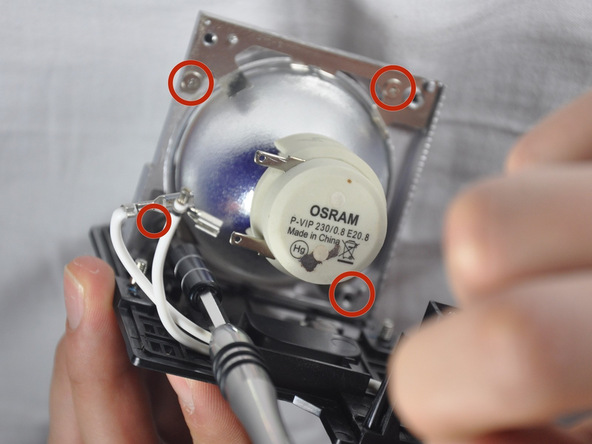
Remove the 4 screws using a Phillips #1 screwdriver to remove the final casing around the bulb.
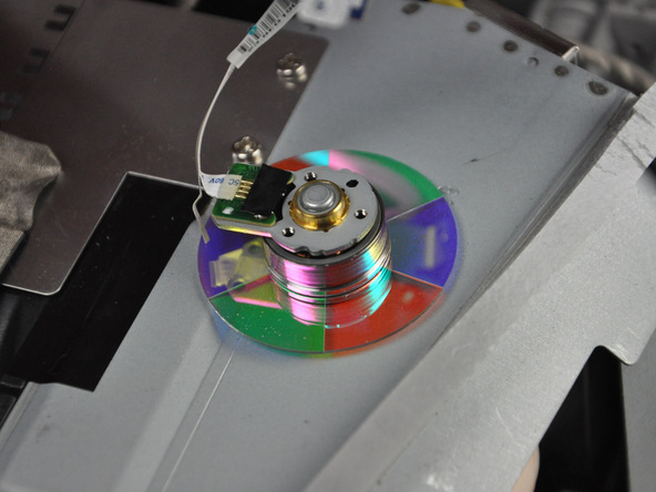
Step 9